


185
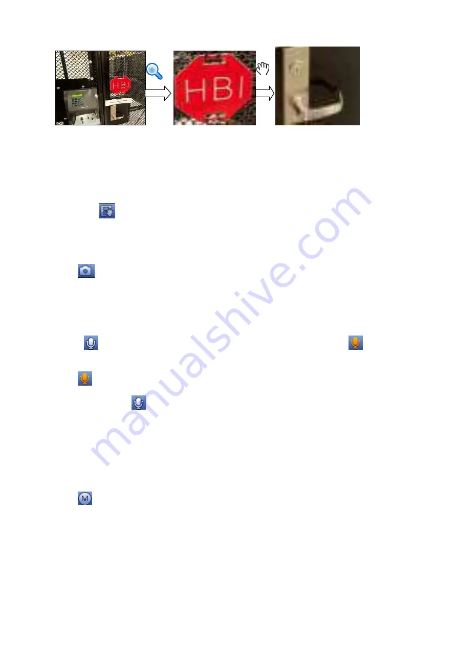
Figure 4-65
Right click mouse to cancel zoom and go back to the original interface.
3) Manual record function
It is to back up the video of current channel to the USB device. System cannot backup the video of
multiple-channel at the same time.
Click button
, system begins recording. Click it again, system stops recoridng. You can find the record
file on the flash disk.
4) Manual Snapshot
Click
to snapshot 1-5 times. The snapshot file is saved on the USB device or HDD. You can go to
the Search interface (chapter 4.5) to view.
5) Bidirectional talk
If the connected front-end device supports bidirectional talk function, you can click this button. Click
button
to start bidirectional talk function the icon now is shown as
. Now the rest
bidirectional talk buttons of digital channel becomes null too.
Click
again, you can cancel bidirectional talk and the bidirectional talk buttons of other digit al
channels become as
.
6) Registration
Shortcut menu. Click it to go to the registration interface to add/delete remote device or view its
corresponding information. Please refer to chapter4.2.2 for detailed information.
7) Switch bit streams
Click
to switch the bit stream type of the main stream and sub stream.
M: Main stream. Its bit streams are big and definition is high. It occupies large network bandwidth
suitable for video wall surveillance, storage and etc.
S: Sub stream. Its definition is low but occupies small network bandwidth. It is suitable for general
surveillance, remote connection and etc. Some series products support two sub streams (S1, S2).
Refer to chapter 4.2.5.1 Encode for detailed information.
4.3.4
Right Click Menu
Summary of Contents for DHI-NVR5224-24P-4KS2
Page 1: ...Network Video Recorder User s Manual V4 3 2...
Page 136: ...124 Figure 3 5 3 6 6 NVR42N Series Please refer to Figure 3 6 for connection sample Figure 3 6...
Page 140: ...128 Figure 3 11 3 6 12 NVR42V 8P Series Please refer to Figure 3 12 for connection sample...
Page 141: ...129 Figure 3 12...
Page 155: ...143 Figure 4 15 Step 2 Click device display edit interface See Figure 4 16...
Page 218: ...206 Figure 4 93 Figure 4 94...
Page 238: ...226 Figure 4 110 Figure 4 111 Figure 4 112...
Page 249: ...237 Figure 4 123 Figure 4 124...
Page 251: ...239 Figure 4 126 Click draw button to draw the zone See Figure 4 127...
Page 255: ...243 Figure 4 130 Click Draw button to draw a zone See Figure 4 131 Figure 4 131...
Page 260: ...248 Figure 4 136 Click draw button to draw the zone See Figure 4 137...
Page 273: ...261 Figure 4 148 Figure 4 149...
Page 274: ...262 Figure 4 150 Figure 4 151...
Page 384: ...372 Figure 5 60 Figure 5 61...
Page 385: ...373 Figure 5 62 Figure 5 63...
Page 409: ...397 Figure 5 96 Figure 5 97...