


13
7 Technical Specification
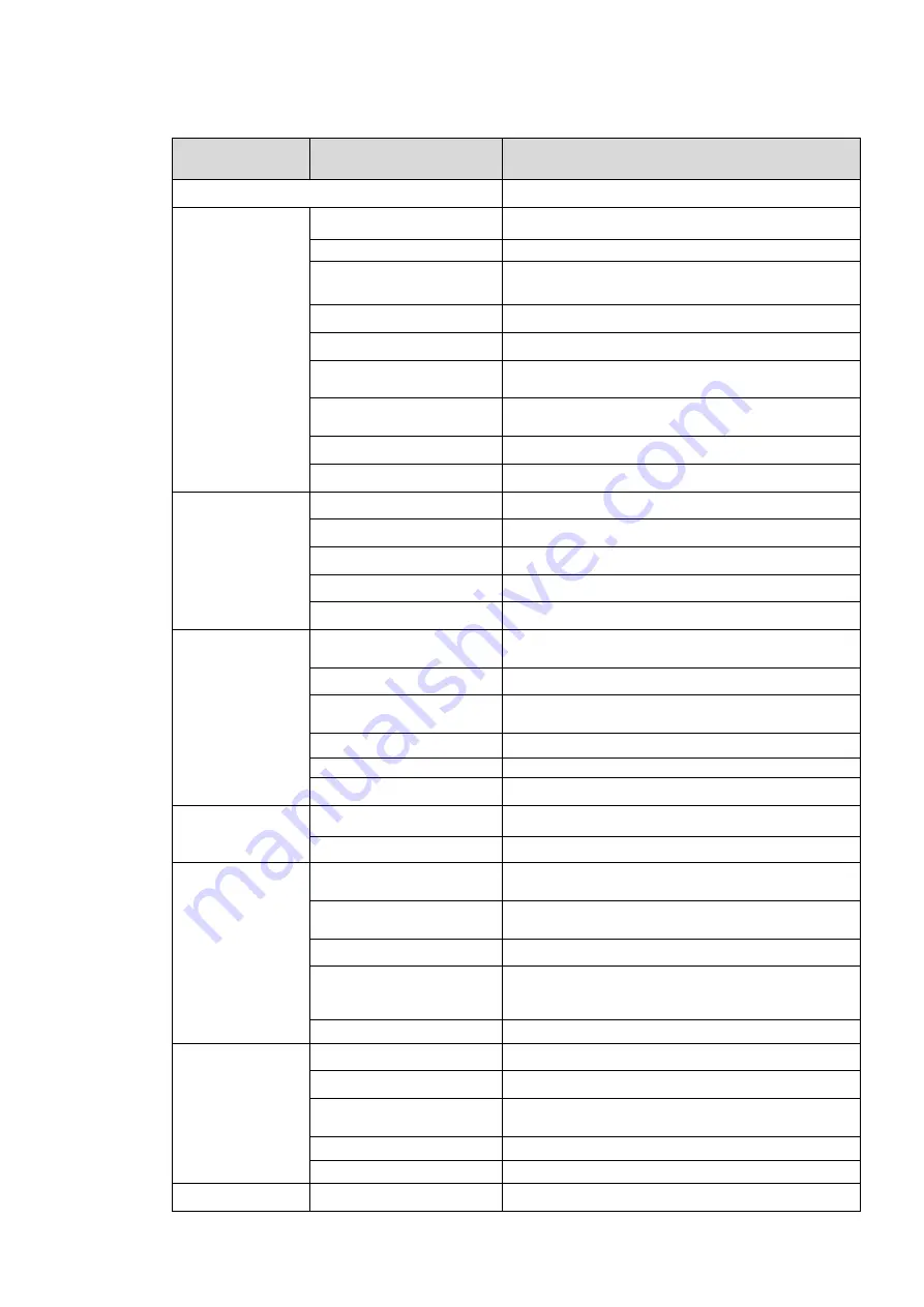
Parameter Type
Parameter Name
Value
Model
DHI-ITC237-PW1A-IRZ
Camera
Sensor
1/1.9 inch CMOS
Shutter
1/12.5
~
1/10000
,
manual or auto
Min Illumination
0.002Lux/F1.2
(
color mode
)
,0.0002Lux/F1.2
(
black white mode
)
Scan
Progressive
Day/Night Mode Switch
IR-CUT motorized cut
Exposure Mode
Support full auto, customized range auto and
customized
White Blance
Support full auto, HUE range auto, and
customized HUE
HLC
Support
Edge Enhance
Support
Lens
Lens Port
φ14
Lens Focus
4mm~8mm
Lens Iris
F1.8
Iris Control
DC drive
Focal Type
Motorized
Image
Image Compression
Standard
JPEG
Image Resolution
1920×1080
Video Compression
Standard
H.264/H.264H/
Bit Stream
H.264 stream adjustable
Video Frame Rate
50s
Video Resolution
1920×1080
Trigger Mode
I/O Coil Trigger
Support
Video Detection
Support
Function
White-list
Max support 10000 vehicles on white-list, may
directly link gateway to output
Intelligent Recognition
Plate recognition, vehicle color recognition,
LOGO recognition
Remote Control
Remote config, control via Web
OSD Info Overlay
Support, may define time, location, direction,
lane no. And etc.
Water-proof
Support, video/picture with water-proof function
Port
Built-in IR
Built-in 2 LED IR lights
Network Port
1, 100/1000M Ethernet port
Alarm Input Port
2-ch, opt coupler input (switch), may used in
coil input
Alarm Output
1-ch, relay output, may used to link gateway
Audio Port
N/A
General
Power
AC 24V


