background image

User's Manual 

259 

Step 5 

Click 

OK

8.8.3 Viewing Cluster Log 

Procedure 

Step 1 

Log in to the PC client. 

Step 2 

Click    on the upper-right corner and then click 

Cluster Management

You can also click 

Cluster Management

 from the configuration list on the home page. 

Step 3 

Set the search period, and then click 

Search

Figure 8-91 Cluster log 


8.9 Extracting Eigenvector Again 

Re-extract Eigenvector of images with unmatched versions, to improve AI analysis accuracy. 


The Extract Eigenvector Again function is triggered automatically after Eigenvector model is 
updated. After the model version update, the system re-extracts face sample databases and 
passerby databases first and then hot data. The hot data includes history capture data. 

Procedure 

Step 1 

Log in to the PC client. 

Step 2 

On the home page, select 

Task Management

 > 

  Extract Eigenvector Again

Step 3 

Click 

  to enable the function. 

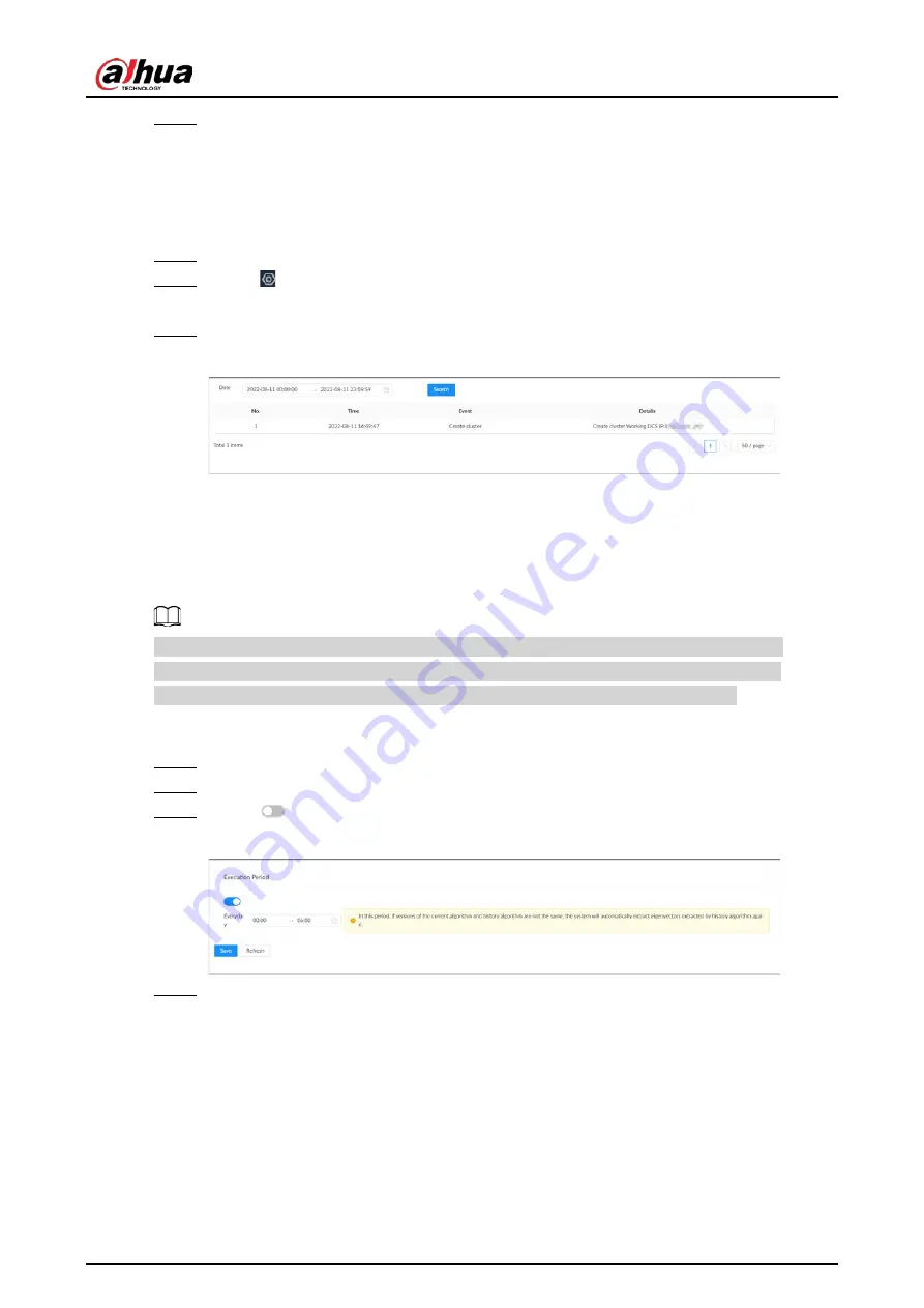
Figure 8-92 Extract Eigenvector again 


Step 4 

Set the start time and end time of the day. 

  The system automatically creates tasks to re-extract Eigenvector of history images with 

unmatched model versions during the period. 

  During the re-extraction period, AI by Recorder is not available. 

Summary of Contents for IVSS

Page 1: ...IVSS User s Manual ZHEJIANG DAHUA VISION TECHNOLOGY CO LTD V6 0 0...

Page 2: ...r function details In the model name R indicates that the model has redundant power In the model name D indicates that the model has an LCD screen Safety Instruction The following signal words might a...

Page 3: ...itch Added algorithm version in the device list Added Re extract Eigenvector Again Optimized people counting call alarm and smoking alarm November 2020 V3 0 4 Optimized storage and recording configura...

Page 4: ...the electronic version and the paper version All designs and software are subject to change without prior written notice Product updates might result in some differences appearing between the actual...

Page 5: ...list Disabled Enabled Refresh the data Cancel the unsaved configuration Page switch page up page down Go to the first page or the last page Filter icon Click it to set filter criteria Click the icon...

Page 6: ...sconnect the power to the Device during an update Make sure the update file is correct because an incorrect file can result in a Device error occurring The system cannot upgrade different types of AI...

Page 7: ...defined range If you did not push the HDD box to the bottom then do not close the handle to avoid damage to the HDD slot Install the Device near a power socket for emergency disconnect It is prohibit...

Page 8: ...User s Manual VII Storage Requirements Store the Device under allowed humidity and temperature conditions...

Page 9: ...3 Dimensions 10 2 3 16 HDD Series 11 2 3 1 Front Panel 11 2 3 2 Rear Panel 12 2 3 3 Dimensions 17 2 4 24 HDD Series 19 2 4 1 Front Panel 19 2 4 2 Rear Panel 20 2 4 3 Dimensions 25 3 Hardware Installat...

Page 10: ...ing Remote Devices 51 5 5 2 1 Quick Add 51 5 5 2 2 Manual Add 53 5 5 2 3 RTSP 55 5 5 2 4 Batch Add 56 6 AI Operations 59 6 1 Overview 59 6 2 Face Detection 60 6 2 1 Enabling the Smart Plan 60 6 2 2 Co...

Page 11: ...Plan 76 6 3 3 3 Configuring Face Detection by Camera 77 6 3 3 4 Configuring Local Face Database 77 6 3 3 4 1 Creating a Face Database 77 6 3 3 4 2 Exporting a Face Database 79 6 3 3 4 3 Adding Face I...

Page 12: ...the Smart Plan 91 6 4 2 Configuring People Counting 91 6 4 3 Configuring In Area No 92 6 4 4 Configuring Queuing Detection 93 6 4 5 Live View 94 6 4 6 Viewing AI Report 94 6 5 Video Metadata 95 6 5 1...

Page 13: ...l Add 116 6 8 3 2 2 Batch Import 117 6 8 3 2 3 Adding from Detection Results 118 6 8 3 3 Managing Vehicle Information 119 6 8 3 3 1 Editing Vehicle Information 119 6 8 3 3 2 Copying Vehicle Informatio...

Page 14: ...33 7 1 1 1 2 Managing View Groups 133 7 1 1 2 View 134 7 1 1 2 1 Creating a View 134 7 1 1 2 2 Editing a View 135 7 1 1 2 3 Opening a View 136 7 1 1 3 View Window 137 7 1 1 3 1 Taskbar 138 7 1 1 3 2 S...

Page 15: ...8 System Configuration 161 8 1 Access Management 161 8 1 1 Viewing Remote Devices 161 8 1 2 Changing IP Address 162 8 1 2 1 Modifying IP of Unconnected Devices 162 8 1 2 2 Modifying IP of Connected De...

Page 16: ...anagement 192 8 3 1 Alarm Actions 192 8 3 1 1 Record 195 8 3 1 2 Buzzer 195 8 3 1 3 Log 195 8 3 1 4 Email 196 8 3 1 5 Preset 196 8 3 1 6 Picture Storage 196 8 3 1 7 Local Alarm Output 197 8 3 1 8 Remo...

Page 17: ...D 216 8 4 1 2 1 Creating RAID 217 8 4 1 2 2 Creating a Hot Standby Disk 220 8 4 1 3 Network Disk 221 8 4 1 3 1 iSCSI Application 221 8 4 1 3 2 iSCSI Management 222 8 4 2 Storage Settings 223 8 4 2 1 C...

Page 18: ...ing Password of Other Users 245 8 6 3 2 Resetting the Password 245 8 6 3 2 1 Leaving Email Address and Security Questions 245 8 6 3 2 2 Resetting Password on Local Interface 246 8 6 3 2 3 Resetting Pa...

Page 19: ...s 267 9 7 1 One click Export 267 9 7 2 Run Log 267 9 8 Maintenance Manager 268 9 8 1 Update 268 9 8 1 1 Updating the Device 268 9 8 1 2 Updating AI Module 268 9 8 1 3 Updating Cameras 269 9 8 2 Defaul...

Page 20: ...D Capacity Calculation 283 Appendix 5 Particulate and Gaseous Contamination Specifications 284 Appendix 5 1 Particulate Contamination Specifications 284 Appendix 5 2 Gaseous Contamination Specificatio...

Page 21: ...l interface web interface and PC client Operation and system configuration in this manual is mainly based on the PC client There might be differences from local or web operations Table 1 1 Login mode...

Page 22: ...ton for at least 4 seconds to shut down the device 2 Alarm indicator light Displays local input alarm status The indicator light is off There is no local alarm input event Red indicator light is on Th...

Page 23: ...2 Power input Inputs 100 240 VAC power 3 AI module indicator light Displays AI module status Yellow light flashes AI module is running properly Yellow light is on AI module is malfunctioning This fun...

Page 24: ...tput VGA2 and HDMI 2 are same source output 10 USB Connects to external devices such as USB storage device keyboard and mouse 11 Network 10 100 1000 Mbps self adaptive Ethernet port Connect to the net...

Page 25: ...User s Manual 5 2 1 3 Dimensions Figure 2 5 Dimension mm inch 2 2 12 HDD Series 2 2 1 Front Panel Figure 2 6 Front panel...

Page 26: ...The device has properly connected to the power source The indicator light is off The device has not connected to the power source Alarm indicator light Displays local input alarm status Green light o...

Page 27: ...2 2 2 Rear Panel Figure 2 7 IVSS7012 rear panel the single power series Figure 2 8 IVSS7012 rear panel the redundant series Figure 2 9 IVSS7012 M rear panel Figure 2 10 IVSS7112 rear panel with singl...

Page 28: ...debug setting IP address and transmitting transparent COM data 5 AUDIO IN Audio input port 6 GND Ground port 7 SAS port SAS extension port It can connect to the SAS extension controller 8 AUDIO OUT Au...

Page 29: ...tive Ethernet port Connect to the network cable 14 Alarm output 8 groups of alarm output ports NO1 C1 NO8 C8 Output alarm signal to the alarm device Please make sure there is power to the external ala...

Page 30: ...User s Manual 10 2 2 3 Dimensions Figure 2 12 Dimensions mm inch...

Page 31: ...ce the front panel lock is secure it can prevent HDD from being stolen or removed by mistake Unlock the front panel lock and remove the front panel you can view 16 HDD slots 2 Power Boot up or shut do...

Page 32: ...one Ethernet port has connected to the network The indicator light is off No Ethernet ports are connected to the network 6 USB port Connects to external devices such as USB storage device keyboard and...

Page 33: ...ear panel redundant power Table 2 6 IVSS7016 rear panel description No Name Description 1 Power input port Inputs 100 240 VAC power 2 AI module indicator light Displays AI module status The yellow lig...

Page 34: ...cts to SATA port or eSATA device 9 USB port Connects to external devices such as USB storage device keyboard and mouse 10 SAS port SAS extension port It can connect to the SAS extension controller 11...

Page 35: ...ator light Displays AI module status The yellow light flashes AI module is running properly The yellow light is on AI module is malfunctioning This function is not available without AI module 3 HDMI p...

Page 36: ...vice keyboard and mouse 10 Network port 10 100 1000 Mbps self adaptive Ethernet port Connects to the network cable 11 Alarm Input 16 groups 1 16 alarm input ports They are corresponding to ALARM 1 ALA...

Page 37: ...User s Manual 17 2 3 3 Dimensions Figure 2 21 Dimensions with LCD mm inch...

Page 38: ...User s Manual 18 Figure 2 22 Dimensions without LCD mm inch...

Page 39: ...ot up or shut down device The power on off button has the indicator light It can display device running status When device is off indicator light is off press the button for a short period to boot up...

Page 40: ...see there are 24 HDDs From the left to the right and from the top to the bottom it ranges from 1 4 5 8 9 12 13 16 17 20 and 21 24 There are two indicator lights on the HDD slot HDD indicator light and...

Page 41: ...Port Description 1 Power input port Inputs 100 240 VAC power 2 Alarm Input 16 groups 1 16 alarm input ports They are corresponding to ALARM 1 ALARM 16 The alarm becomes valid in low level A and B Cont...

Page 42: ...port or eSATA device 7 AUDIO IN Audio input port AUDIO OUT Audio output port 8 RS 232 port RS 232 COM debug It is used for general COM debug setting IP address and transmitting transparent COM data 9...

Page 43: ...ription 1 Power input port Inputs 100V 127V 200 240V AC power 2 Alarm Input 16 groups 1 16 alarm input ports They are corresponding to ALARM 1 ALARM 16 The alarm becomes valid in low level A and B Con...

Page 44: ...ansparent COM data 6 PCI E X4 PCI Express port It supports X4 slot 7 VGA port VGA video output port It outputs analog video signal The VGA port and HDMI 1 port are same source output 8 eSATA port SATA...

Page 45: ...User s Manual 25 2 4 3 Dimensions Figure 2 31 Dimensions with LCD mm inch...

Page 46: ...User s Manual 26 Figure 2 32 Dimensions without LCD mm inch...

Page 47: ...User s Manual 27...

Page 48: ...local retailer or after sales engineer immediately Table 3 1 Checking list No Item Content 1 Whole package Appearance Check whether there is any visible damage Package Check whether there is any accid...

Page 49: ...support different HDD numbers 3 3 1 8 HDD Series Procedure Step 1 Remove the 2 screws on the rear panel Figure 3 2 Remove screws Step 2 Remove the chassis cover in the direction indicated by the arro...

Page 50: ...e 4 screw holes on the HDD to the 4 screw holes on the HDD holder and then tighten the screws Figure 3 5 Install HDD 1 Step 5 Repeat step 4 to install the other HDDs on the holder Figure 3 6 Install H...

Page 51: ...he two holders to the corresponding holes on the chassis place the holders on the chassis and then tighten the screws on the edge of the holders Figure 3 8 Install HDD holders Step 8 Connect HDD signa...

Page 52: ...ely along the upper side of the box and press down to push the HDD down to the lower side of the mounting surface Insert the HDD box into the HDD slot press it to the bottom and then close the box han...

Page 53: ...n on the front panel of IVSS open the handle and then pull out the HDD box Put the HDD into the box along the direction shown in the figure Lock the screws on the back of the HDD box Insert the box in...

Page 54: ...nected to high power load less than 1A When forming output circuit the excessive current should be prevented from causing damage to the relay Use the contactor for isolation when applying high power l...

Page 55: ...User s Manual 35 3 4 1 2 Alarm Port Figure 3 9 8 HDD series Figure 3 10 12 HDD series Figure 3 11 16 24 HDD series 1...

Page 56: ...trol the A B cable of the RS 485 device It is used to connect to the PTZ camera Please parallel connect 120 between A B cables if there are too many PTZ decoders 3 4 1 3 Alarm Input Both NO and NC are...

Page 57: ...damaging the Device see the parameters about relay Table 3 3 Relay parameters of alarm output port Model HRB1 S DC5V Contact material Silver Rated value resistance load Rated power capacity 24 VDC 2A...

Page 58: ...steps are to connect 16 HDD series device See the actual product for detailed information The following figure is for reference only Display mouse and keyboard are needed for local operation Before u...

Page 59: ...ce to international standard For device security connect other cables of the device first and then connect the device to the power socket Boot up might be different depending on the model you purchase...

Page 60: ...ization on the web interface as an example Procedure Step 1 Open the browser enter IP address and then press the Enter key The default IP addresses of network port 1 to network port 4 are 192 168 1 10...

Page 61: ...nually or by synchronizing with NTP server time Manual Settings Select date and time from the calendar NTP Select NTP enter the IP address or domain of the NTP server and then set the automatic synchr...

Page 62: ...See 8 6 3 2 Resetting the Password for detailed information Click to disable the email address or security questions If the email is not set you can only reset the password on the local interface Fig...

Page 63: ...Configure the IP address and DNS server information of the Device according to network planning Make sure that at least one Ethernet port has been connected to the network before you set IP address P...

Page 64: ...MTU Set NIC MTU value The default setup is 1500 bytes We recommend you check the MTU value of the gateway first and then set the MTU value of the Device equal to or smaller than the gateway value whi...

Page 65: ...ollect information such as IP address MAC address and serial number The collected information is only used for remote access Procedure Step 1 On Network page click Next Figure 5 7 P2P access Step 2 Cl...

Page 66: ...C client enter the IP address of the Device and then press Enter When the theme of your computer is not Aero the system will prompt you to switch the theme To ensure video smoothness switch your compu...

Page 67: ...he Password Step 3 Click Login 5 3 3 Logging in to Web Interface You can use the general browser such as Google Chrome Firefox to access the web interface to manage the Device remotely operate and mai...

Page 68: ...User s Manual 48 Figure 5 9 Login web 5 4 Home Page Figure 5 10 Home page...

Page 69: ...u can access the configuration of accounts network events and more by clicking the icon or from the configuration list on the home page 1 0 Login user Change the password lock the user log out restart...

Page 70: ...t The remote device automatically uses the current admin password and email address of the Device 1 To manually configure the password disable Using current device password and password protection inf...

Page 71: ...of adding remote devices Method Description Quick Add Search for the remote devices on the same network and then filter the search results to register the remote devices that you need For details see...

Page 72: ...alize to start initialization For details see 5 5 1 Initializing Remote Devices Modify IP Select one or more remote devices and then click Modify IP to change their IP addresses Initialization Status...

Page 73: ...you do not want to add more remote devices at the moment The Device goes back to the Access Management tab where you can view the added remote devices 5 5 2 2 Manual Add Procedure Step 1 Log in to the...

Page 74: ...the remote device Private is selected by default IP Address Enter the IP address of the remote device Device No Enter the unique device No allocated by the server for the remote device When Manufactur...

Page 75: ...e Method Select a cache method from Self adaptive Realtime and Fluent Remote CH No When the remote device has multiple channels you can select one or more channels of the remote device that you want t...

Page 76: ...rname of the remote device Password Password of the remote device IP address IP address of the remote device Port 554 by default Channel The channel number of the stream media device to be added Subty...

Page 77: ...d Template to download the template On the PC client click at the top of the client select Download to view the storage path On the local interface you can select the file storage path On the web inte...

Page 78: ...mote devices is not filled in completely you can improve it after importing the template Step 7 Select one or more remote devices and then click OK During the adding process click Cancel to cancel add...

Page 79: ...you use AI by Recorder for intelligent detection the camera uploads videos and snapshots and then the Device is responsible for the video analysis job The AI functions might vary depending on the mod...

Page 80: ...rt plan first The Device automatically shows the smart functions available on the connected remote devices Smart plan is available on select remote devices Procedure Step 1 Log in to the PC client Ste...

Page 81: ...e size of detected target is between the maximum size and the minimum size AI by Recorder 1 Click AI by Recorder and then click to enable face detection 2 Click to draw a detection zone on the video C...

Page 82: ...etection images and video 6 2 3 1 Setting Attribute Display You can configure the display rule of face detection results Prerequisites Before using this function make sure that view has been created S...

Page 83: ...Live tab open a view window The video window displays the target boxes of currently detected faces The number next to at the upper right corner of the Live page represents the number of detected faces...

Page 84: ...to insert a USB storage device into the Device Click the icon or double click the record to play back the 10 seconds of video before and after the snapshot Add this image to the face database 6 2 4 Fa...

Page 85: ...ords and then click Export to export snapshots videos or excel After you set alarm linkage snapshot the system exports detected images and panoramic images at the time of snapshot Click the icon or do...

Page 86: ...r the AI Search tab select Search by Face 2 Click and then select Sample Database Image 3 Select a sample database set search conditions and then click Search You can use name or gender to filter the...

Page 87: ...ble related search If related search is enabled the system searches for both face detection results and human detection results Step 7 Click the Device tab Step 8 Select one or more remote devices on...

Page 88: ...cord Support specifying file formats 1 Select one or more face records To export all records select the checkbox next to Select All 2 Click Export and then select the format of the information that yo...

Page 89: ...irst For details see 6 2 1 Enabling the Smart Plan 6 3 2 3 Configuring Remote Face Database The Device can get face databases from the remote devices and also allows creating face databases for remote...

Page 90: ...abase Search for face images Click to search for images in the database by name gender birthday credential type and No and modeling status Arm the face database For details see 6 3 2 4 Configuring Fac...

Page 91: ...u want to upload Click Reselect to cancel the selection of face images 5 Click Save and import face images Point to the face image and then click Upload Again to change it 6 Fill in face image informa...

Page 92: ...mation and add more face images Click Complete to save current face image information and complete registration Bin Import To import face images from another device into the current device you can imp...

Page 93: ...ent Linkage to set alarm actions Step 7 Click Save 6 3 2 5 Live View of Face Comparison You can view real time face comparison images under the Live tab 6 3 2 5 1 Setting Attribute Display You can con...

Page 94: ...ies reach the defined number 2 Select the attributes that you want to display You can select up to 4 attributes 4 attributes have been selected by default To select other attributes cancel the selecte...

Page 95: ...or double click the record to play back the 10 seconds of video before and after the snapshot Add this image to the face database 6 3 2 6 Face Search You can search face records by attributes or by im...

Page 96: ...time of snapshot Click the icon or double click the record to play back the 10 seconds of video before and after the snapshot Add this image to the face database 6 3 2 6 2 Searching by Image Upload f...

Page 97: ...triggers an alarm only when the size of detected target is between the maximum size and the minimum size Step 6 Click Schedule to select a schedule from the drop down list The system triggers corresp...

Page 98: ...Step 5 Click Register or Save and Close Click Register to add face images to the database Click Save and Close if you want to add face images later View face database details and status Figure 6 14 Fa...

Page 99: ...tep 3 Select one or more face databases and then click Export Database Step 4 Click Browse to select the storage path Step 5 Enter a password and then click OK The password is required when you import...

Page 100: ...tabase and then click Manual Add 4 Click and select a face image When the uploaded image is half length photo or full body photo the system automatically processes the image to retain only the face ar...

Page 101: ...hot in the refreshing snapshot list on the right side of the live video and then click Click point to a face snapshot and then click 3 Select a face database and fill in person information 4 Click OK...

Page 102: ...the face image number of the current passerby databases Minimum 10 000 Snapshot Angle Set the allowed pitch angle and yaw angle of the face image The value ranges from 0 through 45 degrees The smaller...

Page 103: ...1 Face database name Click to change the name 2 The number of added face images in the face database and the total number of images that can be added to the database 3 Number of face images that faile...

Page 104: ...atabase If there are too many face images in the face database click to filter the face images Step 5 Click Start The modeling is successful if disappears from the lower left corner of the face image...

Page 105: ...order Prerequisites To use face comparison AI by Recorder you need to enable face detection first For details see 6 2 2 Configuring Face Detection Procedure Step 1 Log in to the PC client Step 2 Click...

Page 106: ...lect a color for the alarm rule box Display Feature Pane Select the checkbox to enable the features pane The features pane appears on the live video once there is an alarm 3 Click Select next to Event...

Page 107: ...I by Camera you need to enable the corresponding smart plan first For details see 6 2 1 Enabling the Smart Plan 6 3 4 3 Configuring Face Comparison by Camera Configure face comparison rules For detail...

Page 108: ...configuration list on the home page Step 3 Select a remote device on the device tree and then select Smart Plan Face Detection Step 4 Click AI by Recorder and then click to enable face detection Step...

Page 109: ...o select a schedule from the drop down list The system triggers corresponding alarm actions only during the alarm deployment period You can select an existing schedule from the Schedule drop down list...

Page 110: ...mera Figure 6 24 Configure video metadata AI by recorder Figure 6 25 Configure face comparison AI by recorder 6 3 6 2 Enabling the Smart Plan To use AI by Camera you need to enable the corresponding s...

Page 111: ...stem counts the number of people in and out of the detection area When the number of entry exit or stay reaches the threshold an alarm is triggered Procedure Step 1 Log in to the PC client Step 2 Clic...

Page 112: ...iguring In Area No The system counts the number of people in and out of the detection area When the number of entry or exit is larger or smaller than the threshold or when the dwell time of any person...

Page 113: ...the threshold an alarm will be triggered Step 7 Click Schedule to select a schedule from the drop down list The system triggers corresponding alarm actions only during the alarm deployment period You...

Page 114: ...person in the area is longer than the threshold an alarm will be triggered Step 7 Click Schedule to select a schedule from the drop down list The system triggers corresponding alarm actions only duri...

Page 115: ...ated Operations Point to the report and then the report shows the details at that time point Drag the gray scroll bar under the ordinate to view the statistics for different time periods Click to view...

Page 116: ...detection 4 Select an alarm type All An alarm is triggered when a target is detected Match Attributes Alarm An alarm is triggered when the detected target matches the defined attributes Mismatch Attr...

Page 117: ...p 5 Configure AI attributes settings With AI Attributes Settings enabled by default when the system detects a target a features panel appears on the live video You can configure the style of the featu...

Page 118: ...Different detection targets correspond to different colors of target boxes You can view the statistics on the detected targets at the upper right corner of the Live page face human motor vehicle non...

Page 119: ...ted face to the face database 6 5 4 AI Search You can search for video metadata detection records 6 5 4 1 Human Search Search for human detection results 6 5 4 1 1 Searching by Attributes Procedure St...

Page 120: ...the defined attributes Step 7 Click Search If face is captured the human and face snapshots are displayed If no face is captured the human snapshot and human attributes are displayed Related Operation...

Page 121: ...on the home page Step 3 Select Search by Human Search by Image Step 4 Upload human images You can upload up to 50 images After uploading face images you can select up to 10 images for search at one t...

Page 122: ...2 Click on the upper right corner of the Live page or select AI Search on the home page Step 3 Select Search by Vehicle and then select one or more remote devices Step 4 Under the Attribute tab set Ev...

Page 123: ...Icon Operation Click the icon to select the record To select all the records at a time select the checkbox next to Select All Export the snapshot video and video player To export in batches select mul...

Page 124: ...results Icon Operation Click the icon to select the record To select all the records at a time select the checkbox next to Select All Use this image to search all channels for similar records Export...

Page 125: ...ct a remote device on the device tree and then select Smart Plan IVS Step 4 Select AI By Camera Global Config Step 5 Drag to adjust sensitivity Step 6 Calibrate horizontal and vertical scales 1 Click...

Page 126: ...riggered and then the system performs configured alarm linkages Fast Moving When the target moves fast in the detection area an alarm is triggered and then the system performs configured alarm linkage...

Page 127: ...the detected target size is between the maximum size and the minimum size AI by Recorder 1 Click AI by Recorder 2 Click to enable IVS 3 Click Add Rule and then select Tripwire 4 Click to enable the d...

Page 128: ...next to Event Linkage to set alarm actions Step 8 Click Save Repeat Step4 through Step7 to add multiple detection rules You can add up to 10 detection rules for a remote device 6 6 3 Live View of IVS...

Page 129: ...User s Manual 109 Figure 6 29 Human...

Page 130: ...o 4 attributes 4 attributes have been selected by default To select other attributes cancel the selected attributes and then select the ones you need 3 On the AI Attributes section select the attribut...

Page 131: ...4 IVS Search Search for IVS records Procedure Step 1 Log in to the PC client Step 2 Click on the upper right corner of the Live page or select AI Search on the home page Step 3 Select IVS and then se...

Page 132: ...n also click Event from the configuration list on the home page Step 3 Select a remote device on the device tree and then select Smart Plan ANPR The function is enabled by default and cannot be disabl...

Page 133: ...onfigure the style of the features panel and the attributes that you want to display 1 Select the panel styles 2 Select the attributes that you want to display You can select up to 4 attributes 4 attr...

Page 134: ...on results For details see 6 5 4 2 Vehicle Search 6 8 Plate Comparison The system detects license plates using video metadata or ANPR and then compares the detected plate number with the ones in the d...

Page 135: ...tus Database name Number of vehicle plates in the database Allowlist Blocklist The database type The database is not linked to any channel for plate comparison If armed the linked channel will be disp...

Page 136: ...l Add Step 5 Set the parameters Figure 6 34 Plate registration Table 6 25 Vehicle register parameters Parameters Description Region The country or region that the vehicle belongs to Name Driver s name...

Page 137: ...ck Save Save the current vehicle information and close the Plate Registration window 6 8 3 2 2 Batch Import Import vehicle information in batches We recommend this method when you want to add plenty o...

Page 138: ...logo type color and plate color fill in the corresponding value You can search for the value in the Template Fields Search section on thePlate Registration window Step 5 On the Plate Registration win...

Page 139: ...the home page select File Management Plate Database Config Step 3 Double click a database Step 4 Point to a record and then click Step 5 Modify vehicle information according to actual needs Step 6 Cl...

Page 140: ...oint to a plate record and then click at the upper right corner to delete it Delete in batches Point to the database and then click at the upper left corner to select the face record Select multiple p...

Page 141: ...m the Schedule drop down list You can also add a new schedule Step 7 Configure event linkage for unregistered vehicles An alarm is triggered when the detected vehicle information is not found in the p...

Page 142: ...appears on the live video once there is an alarm 3 Click Select next to Event Linkage to set alarm actions Step 9 Click Save 6 8 5 Live View of Plate Comparison View plate comparison results under the...

Page 143: ...have been selected by default To select other attributes cancel the selected attributes and then select the ones you need 3 On the AI Attributes section select the attribute groups for video metadata...

Page 144: ...e or select AI Search on the home page Step 3 Select Search by Vehicle and then select one or more remote devices Step 4 Under the Attribute tab set Event Type to Plate Comparison Step 5 Set vehicle a...

Page 145: ...following icons are displayed Table 6 28 Management of search results Icon Operation Click the icon to select the record To select all the records at a time select the checkbox next to Select All Expo...

Page 146: ...for crowd monitoring Procedure Step 1 Log in to the PC client Step 2 Click on the upper right corner and then click Event You can also click Event from the configuration list on the home page Step 3 S...

Page 147: ...a view window The video image of the view is displayed The video shows people numbers and distribution status in the detection zones in real time The frame around the detection zone flashes red when t...

Page 148: ...ag the corners to adjust the detection zone Step 7 Set the sensitivity and minimum duration Sensitivity The higher the sensitivity the easier the call action is detected but meanwhile the higher proba...

Page 149: ...ng the Smart Plan To use AI by Camera you need to enable the corresponding smart plan first For details see 6 2 1 Enabling the Smart Plan 6 11 2 Configuring Smoking Alarm Configure smoking alarm rules...

Page 150: ...a view window The video image of the view is displayed When an alarm is triggered the detection zone flashes red 6 11 4 Smoking Alarm Search Search for videos or images of smoking alarm Procedure Step...

Page 151: ...and then click or to hide or display the left and right columns Figure 7 1 Live view Table 7 1 Live page description No Description 1 Device tree Displays added remote devices 2 View zone Displays the...

Page 152: ...the number of detected targets face human motor vehicle non motor vehicle 9 Set attribute display Go to AI Search 7 1 1 View Management A view is composed of video images of several remote devices Go...

Page 153: ...der View Group 2 7 1 1 1 1 Creating a View Group Procedure Step 1 Log in to the PC client Step 2 Under the Live tab click View Group or a view group under it and then click Add Group You can also righ...

Page 154: ...devices to the view so that you can view the live videos from several channels at the same time Prerequisites Remote devices have been added See 5 5 2 Adding Remote Devices for detailed information P...

Page 155: ...name See 7 1 1 2 2 Editing a View for detailed information Open Open a view to watch real time video of remote devices in the view See 7 1 1 2 3 Opening a View for detailed information Rename Right cl...

Page 156: ...ed background color Change the window size Drag the edges of the video window to adjust its size and then click OK Save the view as a new one Change the view name in and then click OK 7 1 1 2 3 Openin...

Page 157: ...nformation Zoom in video window When there are more than 9 video windows click one video window to display it at the center of all windows in the zoom in mode Click any other blank position to restore...

Page 158: ...User s Manual 138 Figure 7 5 View window 7 1 1 3 1 Taskbar Log in to the PC client under the Live tab open a view and then point to a video window The taskbar is displayed Figure 7 6 View window...

Page 159: ...ved on the Device You can search for and export videos under the Search tab PC client The default storage path of videos is C Program Files x86 PCAPP video Manual snapshot The snapshot storage path va...

Page 160: ...play space Audio Set an audio output mode from Audio 1 Audio 2 Mixing and Close Fisheye Dewarp Set installation methods and display modes of fisheye cameras This function is only available on fisheye...

Page 161: ...an 10 targets in the frame the system prompts you to narrow the search zone Step 5 Select a target type Step 6 Click OK The system automatically searches all channels for similar snapshots within the...

Page 162: ...in to the PC client Step 2 Under the Live tab open a view Step 3 Right click the live video and then select Smart Tracking ON Step 4 Select the tracking method Manual positioning Click a spot or sele...

Page 163: ...cedure Step 1 Log in to the PC client Step 2 Open a view under the Live client Step 3 Click at the upper right corner of the view window to enable the Talk function Click again to disable the function...

Page 164: ...on of the remote device is red the remote device is offline For example If appears the remote device is abnormal alarming and more Point to to view the detailed information Mouse operations Point to t...

Page 165: ...the PTZ direction Click the arrows to control the PTZ direction Click to enable 3D positioning function Click to enable auto focus and then the camera image becomes focused automatically Click to ente...

Page 166: ...and more You can use the direction and confirm buttons to set the remote device Procedure Step 1 Log in to the PC client Step 2 Under the Live tab open a view and then select a remote device on the v...

Page 167: ...the saved information of a specific position angle and focal length of the PTZ camera You can set a preset so that you can quickly adjust the PTZ to the desired position when needed Procedure Step 1...

Page 168: ...og in to the PC client Step 2 Under the Live tab open a view Step 3 Select the video window of a PTZ camera Step 4 On the PTZ panel click Step 5 Click enter the name of the new tour group and then cli...

Page 169: ...op Record Step 6 Execute the pattern 1 Hover over the name of the pattern 2 Click next to the name of the tour group The PTZ camera executes the actions in the pattern 3 Click to stop the PTZ actions...

Page 170: ...p 1 Log in to the PC client Step 2 Under the Live tab open a view Step 3 Select the video window of a PTZ camera Step 4 On the PTZ panel click Step 5 Click to enable the function 7 2 Recorded Files Yo...

Page 171: ...k to play back the videos Timeline playback Play back videos automatically File playback The videos files are displayed by channel or by time Click a file to play back You can click to divide a video...

Page 172: ...want to cancel synchronization click Play back video file at a slow speed The slow speed includes1 2 1 4 1 8 and1 16 Click the icon once and then the playback speed becomes one level slower Play the...

Page 173: ...recording time Right click the playback window to bring up the shortcut menu Original Set video window scale On The system automatically adjusts video window scale according to the video resolution Cl...

Page 174: ...the video After playback you can use time or the tag keywords to search for the corresponding video and then play Procedure Step 1 Log in to the PC client Step 2 On the home page select Search Step 3...

Page 175: ...e image type and snapshot time Procedure Step 1 Log in to the PC client Step 2 On the home page select Search Step 3 Select a remote device and then click the Picture tab Step 4 Select an image type M...

Page 176: ...evice and then select a file format 4 Click Format to format the selected storage device Please be advised that formatting the storage device will clear all data on it 5 Click Start Make sure that an...

Page 177: ...bnormal the abnormal watermark and its type are displayed 7 2 7 2 1 1 Face Comparison Through 1 1 face comparison the system analyzes the similarity between two images Procedure Step 1 Log in to the P...

Page 178: ...a remote device 1 Under the Remote tab select a remote device from the camera list 2 Click Import 3 Select an audio file and then click Open Step 4 Click Import to select the audio files that you wan...

Page 179: ...nected monitors Click on the local interface The 1 3 monitors represent monitors connected to HDMI 1 HDMI 3 The main screen refers to the monitor connected to VGA or HDMI 1 port The monitors connected...

Page 180: ...ponding system message Click Clear to clear all system messages under current tab For example you can click Clear under the All tab to clear all system messages or click Clear under the System Error t...

Page 181: ...nd configurations and export their information Figure 8 1 Access management Click on the lower left corner or click Add to add remote devices to the Device For details see 5 5 2 Adding Remote Devices...

Page 182: ...can click to filter the remote devices 8 1 2 Changing IP Address Modify IP address of the remote devices that are connected or not connected to the Device 8 1 2 1 Modifying IP of Unconnected Devices P...

Page 183: ...arch results Step 5 Select one or more remote devices and then click Modify IP You can only modify the IP address of initialized devices You can only modify the IP address of remote devices that are u...

Page 184: ...tches the system automatically skips the conflicted IP and begins the allocation according to the incremental value If you want to change IP addresses of multiple remote devices make sure that they sh...

Page 185: ...of the remote device and then click Next Enter incremental value only when you want to change IP addresses of several devices at the same time The system will allocate IP address one by one with the f...

Page 186: ...hen click Save 8 1 3 2 Managing Video Channels of Multichannel Devices When the connected remote device has multiple video channels you can add or delete the video channels connected to the Device Pro...

Page 187: ...Step 4 Select a remote device from the device tree and then click the Video tab Figure 8 7 Video Step 5 Set the parameters under the Main Stream Sub Stream 1 and Sub Stream 2 tab This section uses con...

Page 188: ...id and fluent the video Stream Mode Select a stream mode CBR The bit rate changes slightly around the defined value We recommended you select CBR when there might be only small changes in the monitori...

Page 189: ...OSD tab Figure 8 8 OSD Step 4 Configure OSD information Device name 1 Click to enable OSD of device name 2 Click 3 Enter the device name 4 Drag the text box to the proper position Time 1 Click to enab...

Page 190: ...ameters Procedure Step 1 Log in to the PC client Step 2 Click on the upper right corner of the page and then click Access Management You can also click Access Management from the configuration list on...

Page 191: ...nformation of remote devices such as the connection type and cache method Procedure Step 1 Log in to the PC client Step 2 Click on the upper right corner of the page and then click Access Management Y...

Page 192: ...remote devices import the exported information of remote devices to recover quickly Procedure Step 1 Log in to the PC client Step 2 Click on the upper right corner of the page and then click Access M...

Page 193: ...ice is offline Right click an offline remote device and then select Connect to connect the remote device Right click an online remote device and then select Disconnect to disconnect the remote device...

Page 194: ...her devices on the network 8 2 1 1 Configuring IP Address Set IP address of the Device DNS server information and other information according to network planning Make sure that at least one Ethernet p...

Page 195: ...slightly and enhance network transmission efficiency Please be advised that changing MTU value might result in NIC restart network offline and affect current running operation Step 6 Click OK Step 7...

Page 196: ...Link aggregation The Device bonds several NICs and all NICs are working together to share the network load The system allocates data to each NIC according to your allocation strategy Once the system...

Page 197: ...ng on the aggregation mode you have selected The following figure is the load balance setting page Figure 8 14 Edit load balance 5 Set parameters Table 8 6 NIC parameters description Parameters Descri...

Page 198: ...ice equal to or smaller than the gateway value which helps to reduce the packets slightly and enhance network transmission efficiency Please be advised that changing MTU value might result in NIC rest...

Page 199: ...Step 4 Configure the parameters When you log in via TCP you do not need to log in again to make you changes in max connection RTSP port and UDP port become effective When you log in by other methods...

Page 200: ...ding services of the ports 8 2 2 Network Apps Set the parameters of network applications so that system can connect to other devices 8 2 2 1 P2P P2P is a peer to peer technology You can scan the QR co...

Page 201: ...the app 8 2 2 2 Register Register the Device on a designated proxy server so that client software can access the Device through the proxy server Procedure Step 1 Log in to the PC client Step 2 Click o...

Page 202: ...e Step 6 Click Apply 8 2 2 3 Email Configure email information When an alarm event linked with email occurs the system automatically sends emails to the user Please be advised that device data will be...

Page 203: ...Click to delete the added receiver Select a receiver and then click Delete to delete the selected receiver Step 7 Click Apply Step 8 Optional Test the email sending function 1 In the box next to Test...

Page 204: ...8 2 2 5 UPnP Through the UPnP Universal Plug and Play protocol you can establish a mapping relationship between the LAN and the WAN The WAN user can use the WAN IP address to directly access the Devi...

Page 205: ...from the configuration list on the home page Step 3 Select NETWORK Network Apps UPnP Figure 8 21 UPnP Step 4 Set parameters Table 8 11 UPnP parameters Parameter Description Port Mapping Click to enab...

Page 206: ...he TCP UDP WAN and LAN ports must be consistent and cannot be modified Step 5 Click Apply Enter http WAN IP WAN port number in the browser to access the Device with the corresponding port number on th...

Page 207: ...rsion For data security we recommend V3 Step 6 Set parameters For Trap Address enter the IP address of the computer installed with the MG SOFT MIB Browser Leave the other parameters as default Table 8...

Page 208: ...ast 8 digits Read Write User The username is private by default If you log in using this username you have the read and write permission The name can only contain numbers letters and underscores Authe...

Page 209: ...p 4 Click to enable the DDNS function After you enable the DDNS function the third party server might collect your device information Pay attention to privacy security Step 5 Set the parameters Table...

Page 210: ...5 255 for the Device Procedure Step 1 Log in to the PC client Step 2 Click on the upper right corner and then click Network You can also click Network from the configuration list on the home page Step...

Page 211: ...e best path for data transmission Procedure Step 1 Log in to the PC client Step 2 Click on the upper right corner and then click Network You can also click Network from the configuration list on the h...

Page 212: ...ent depending on the model you purchased means that the corresponding alarm event has been enabled means that AI by Camera has been enabled means that AI by Recorder has been enabled means that both A...

Page 213: ...e such as IPC has been added See 5 5 2 Adding Remote Devices for detailed information Buzzer The system activates a buzzer alarm when a linkage event occurs Log The system notes down the alarm informa...

Page 214: ...alarms The Device is connected with alarm output device See 3 4 1 4 Alarm Output Remote Device Alarm Output The remote device has been added and the remote device is connected with an alarm output de...

Page 215: ...formation Procedure Step 1 On the alarm configuration page click Select next to Event Linkage and then select Record Figure 8 28 Record Step 2 Set the time length of recording after the event moment S...

Page 216: ...t when a linkage event occurs Make sure that the PTZ device has been added and preset has been added See 5 5 2 Adding Remote Devices for detailed information Procedure Step 1 On the alarm configuratio...

Page 217: ...ice Alarm Output Set remote device alarm output The system links the corresponding remote alarm output device to generate an alarm when a linkage event occurs Make sure that the remote device has been...

Page 218: ...configuration page click Select next to Event Linkage and then select Audio Linkage Figure 8 33 Audio linkage Step 2 Select the audio file and then set the play mode Play Times After the event ends th...

Page 219: ...available when AI by camera is used for IVS detection and the camera supports this function Procedure Step 1 On the alarm configuration page click Select next to Event Linkage and then select Remote W...

Page 220: ...normal Events Set the alarms for abnormal events such as no disk storage errors and IP conflict Table 8 16 Abnormal events Name Description No Disk The system triggers an alarm when there is no disk I...

Page 221: ...gers an alarm It is enabled by default Power alarm When the power supply is abnormal the system triggers an alarm It is disabled by default AI module temp When the temperature of the AI module is high...

Page 222: ...offline alarm for IVSS If you have not set offline alarm for a remote device once the remote device is disconnected from the system the system adopts the alarm strategy for IVSS to trigger an alarm P...

Page 223: ...larm actions Step 8 Click Save 8 3 2 4 Configuring Smart Plan You can view smart plans and configure entries frequency and video quality analytics 8 3 2 4 1 Viewing Smart Plans After you add the remot...

Page 224: ...click Event You can also click Event from the configuration list on the home page Step 3 Select the root node on the device tree Step 4 Select Smart Plan Entries Frequency Figure 8 38 Entries frequen...

Page 225: ...the features panel on the right side of the video window displays a high frequency tag You can find the tagged faces using live view or AI search For details about live view see 6 2 3 Live View of Fa...

Page 226: ...ule from the Schedule drop down list You can also add a new schedule Step 8 Click Select next to Event Linkage to set alarm actions Step 9 Click Save Viewing AI Report You can view the daily monthly o...

Page 227: ...iggered Make sure that the Device is connected with an alarm input device The Device supports 16 channel alarm input Configure according to actual port of alarm input device This section uses alarm in...

Page 228: ...only one alarm event during this period Step 7 Click Schedule to select a schedule from the drop down list The system triggers corresponding alarm actions only during the alarm deployment period You...

Page 229: ...t corner and then click Event You can also click Event from the configuration list on the home page Step 3 Select a remote device from the device tree Step 4 Select Video Detection Motion Detection Fi...

Page 230: ...cted target occupies 10 or more of the detection zone the system triggers an alarm Step 8 Click Schedule to select a schedule from the drop down list The system triggers corresponding alarm actions on...

Page 231: ...When the remote device is disconnected from the IVSS the system triggers an alarm Procedure Step 1 Log in to the PC client Step 2 Click on the upper right corner and then click Event You can also cli...

Page 232: ...to the Device If the remote device has multiple IO ports you can set the alarm input event for each port Procedure Step 1 Log in to the PC client Step 2 Click on the upper right corner and then click...

Page 233: ...l perform an alarm linkage action Temperature alarm When the thermal camera detects that the temperature is above or below the threshold value the alarm signal is transmitted to the Device and the Dev...

Page 234: ...k and routine inspection and you can obtain real time storage status of the Device and avoid data loss Pre check During device operation the system automatically detects disk status in case of change...

Page 235: ...ntial problems The system monitors the disk running status and compares with the specified safety value Once the status is higher than the specified value the system displays alarm information to guar...

Page 236: ...disk or you cannot properly use the disk you can try to fix the file system Log in to the PC client Click on the upper right corner and then select Storage Storage Resource Disk Select one or more di...

Page 237: ...ance Create RAID according to your actual requirements Please be advised that creating RAID will clear all data on the member disks Procedure Step 1 Log in to the PC client Step 2 Click on the upper r...

Page 238: ...Self adaptive The system automatically adjusts RAID synchronization speed according to current business load When there is no external business the synchronization speed is high When there is external...

Page 239: ...dify the RAID parameters Related Operations After creating RAID you can view RAID disk status and details clear up RAID and repair file system Table 8 24 RAID operations Name Operation View the status...

Page 240: ...tep 3 Select Storage Resource RAID Hot Standby Step 4 Click Add Step 5 Select hot standby creation type Global Hot Standby Create a hot standby disk for all RAID groups Select the storage device and t...

Page 241: ...vice information on the network hard disk through the iSCSI protocol 8 4 1 3 1 iSCSI Application Log in to the PC client Click on the upper right corner and then select Storage Storage Resource Networ...

Page 242: ...the upper right corner and then click Storage You can also click Storage from the configuration list on the home page Step 3 Select Storage Resource Network Disk iSCSI Management Step 4 Click Add Fig...

Page 243: ...details see 8 4 2 1 Configuring Disk Groups 8 4 2 Storage Settings 8 4 2 1 Configuring Disk Groups The installed disks and created RAID groups are allocated to group 1 by default You can create more...

Page 244: ...ups for the disk group Add disks or RAID groups to the current disk group Click Add select one or more disks or RAID groups and then click OK Move disks or RAID groups to another disk group One by one...

Page 245: ...balance After you enable load balance the system automatically moves videos from ineffective disk groups and evenly allocates them to functional groups 8 4 2 2 Recording Control Configure recording mo...

Page 246: ...led at the same time Figure 8 56 Recording Mode Step 5 Click Apply 8 4 2 2 2 Configuring Recording Schedule Configure video and picture recording schedules so the Device records videos and captures pi...

Page 247: ...Network Replenishment When the network connection between the Device and IPC fails the IPC continues to record videos and store videos on the SD card on the camera When network recovers the Device dow...

Page 248: ...2 Click on the upper right corner and then click Storage You can also click Storage from the configuration list on the home page Step 3 Select Storage Basic Step 4 Set storage mode Overwrite When fre...

Page 249: ...r right corner and then click Storage You can also click Storage from the configuration list on the home page Step 3 Select Storage Basic Step 4 Select an image storage strategy from Linkage Configura...

Page 250: ...time period Step 7 Click Add The system downloads files recorded on the selected channels during the defined period Select a transfer task click Delete to delete it A task in progress cannot be delete...

Page 251: ...tem will not be checked in subsequent scans Click Rejoin Detection to include the ignored item into the security scan Click Optimize to go to the corresponding configuration page where you can optimiz...

Page 252: ...unction is disabled by default For data security we recommend you disable this function when it is not needed CGI After this function is enabled a third party platform can connect the Device through C...

Page 253: ...TPS HTTPS can use the reliable and stable technological means to guarantee user information and device security and communication data security After you install the certificate and enable HTTPS funct...

Page 254: ...t a firewall mode All All hosts can access the Device Allowlist The hosts on the allowlist can access the Device Blocklist The hosts on the blocklist are prohibited to access the Device Allowlist and...

Page 255: ...device account and login of the ONVIF account is enabled by default and cannot be disabled Step 4 Click Apply Step 5 Optional Click to go to the Event page where you can configure the lockout alarm e...

Page 256: ...ense Sync Time Figure 8 69 Sync time Step 3 Click to enable time synchronization restriction Step 4 Select Allowlist or Blocklist Allowlist Hosts on the allowlist have the permission to synchronize ti...

Page 257: ...ates 8 5 4 1 Installing the Device Certificate A device certificate is a proof of device legal status For example if you want to access IVSS through a browser you need to install the root certificate...

Page 258: ...8 72 Certificate information 3 Click Create and install certificate Apply for and import a certificate 1 Select Apply for CA Certificate and Import Recommended and then click Next 2 Enter the informa...

Page 259: ...or the private key 5 Click Import and Install Related Operations You can edit and download the installed certificate Edit Click Enter Edit Mode enter a custom name for the certificate and then click S...

Page 260: ...Encryption The Device supports audio and video encryption during data transmission Procedure Step 1 Log in to the PC client Step 2 On the home page select Security Video Encryption Encrypted Transmis...

Page 261: ...user when a security error occurs Procedure Step 1 Log in to the PC client Step 2 On the home page select Security Security Warning Figure 8 76 Security warning Step 3 Click to enable the function St...

Page 262: ...Select the root node at the upper left corner and then click at the lower left corner Step 4 Enter the login password of the current account and then click OK Figure 8 77 User group property Step 5 C...

Page 263: ...admin and Onvif user groups cannot be deleted 8 6 2 Adding Device Users A device user can access and manage the Device The default administrator is admin You can add more users with different permiss...

Page 264: ...d and then confirm it Set a strong password according to the on screen prompt Confirm Password Description Enter descriptions for the user Step 6 Click the Permission to view the permissions of the us...

Page 265: ...Other Users Only users in the admin group have the permission to change passwords of other users Procedure Step 1 Log in to the PC client Step 2 Click on the upper right corner and then click Account...

Page 266: ...the email address and then click Next Step 5 Select the reset mode and then reset the password Email Follow the on screen instructions to get the security code in your linked email address After that...

Page 267: ...t when you point to on the login page the system pops up a prompt to remind you of the password The password prompt is available only on the login page of the local interface Step 7 Click Confirm Modi...

Page 268: ...word Description Enter descriptions for the user Step 6 Click Apply Related Operations Select an ONVIF user and then click to delete it The admin ONVIF user cannot be deleted 8 7 System Settings Log i...

Page 269: ...or the Device Logout Time Enter the time of inactivity before logout The Device logs out automatically after the period of inactivity If you select None the Device does not automatically log out Sync...

Page 270: ...P function the Device can automatically synchronize time with the NTP server Procedure Step 1 Log in to the PC client Step 2 Click on the upper right corner and then click System You can also click Sy...

Page 271: ...nable this function IVSS detects the system time of remote devices once in every interval When the time of a remote device is inconsistent with IVSS time IVSS will calibrate the time of the remote dev...

Page 272: ...MI ports can output different video sources means the monitor is connected and enabled means the monitor is connected but has not enabled means no monitor is connected Step 4 Select a monitor and then...

Page 273: ...dule 1 Click Create 2 Click to edit the schedule name Step 4 Set the validity periods Always The schedule is always effective Custom Customize validity periods for the schedule Click the time bar and...

Page 274: ...during the failure to the main device which then takes over the job again In the N M cluster system there is a management server the DCS Dispatching Console server which is responsible for timely and...

Page 275: ...on the upper right corner and then click Cluster Management You can also click Cluster Management from the configuration list on the home page Step 4 Click Cluster Setting and then click Enable Clust...

Page 276: ...the login username and password of the Device Password Enable Cluster Select the checkbox to enable cluster and then enter the cluster IP address subnet mask and gateway Cluster IP is a virtual IP tha...

Page 277: ...rt Enter the port number It is 37777 by default Username Enter the login username and password of the Device Password 3 Click OK Step 7 Click Next Step 8 Set the arbitrage IP When there are only 2 dev...

Page 278: ...need to be transferred back to the main device Procedure Step 1 Log in to the PC client Step 2 Click on the upper right corner and then click Cluster Management You can also click Cluster Management...

Page 279: ...Again function is triggered automatically after Eigenvector model is updated After the model version update the system re extracts face sample databases and passerby databases first and then hot data...

Page 280: ...ance 9 1 Overview Log in to the PC client On the home page select Maintain Overview Figure 9 1 Overview Table 9 1 Overview No Function Description 1 Overview View device version and the number of onli...

Page 281: ...lick click to enable device positioning and then set the interval at which the positioning indicator light of the Device flashes The flashing indicator light helps you quickly find the Device Click to...

Page 282: ...9 2 4 Viewing Storage Information Log in to the PC client On the home page select Maintain System Info Storage Info You can view the storage information of each channel Figure 9 3 Storage information...

Page 283: ...rk Maintenance 9 4 1 Online User Manage the online user that can access the Device You can block a user from access for a period of time During the block period the selected user cannot access the Dev...

Page 284: ...me page select Maintain Network Maintenance Network Test Figure 9 6 Network test Step 3 In the Network Test section enter the target address and then click Test After testing is completed the test res...

Page 285: ...9 5 2 SSD Health Detection On the home page select Maintain Disk Maintenance SSD Health Detection and then you can view the storage allocation and remaining P E cycle of SSD Figure 9 8 SSD health det...

Page 286: ...ems in time 9 6 1 Log Classification Table 9 2 Log categories Log Type System log Logs of system running status file management hardware detection and scheduled task User operation log User operation...

Page 287: ...Keep the unencrypted logs safe to prevent data leakage Clear logs Click Clear all to clear all the logs You might be unable to track the reasons of system errors if you clear logs 9 7 Intelligent Dia...

Page 288: ...name of the update file is bin Prerequisites You need to obtain the correct update file and save it in the corresponding path When operating on the local interface save the update file in the USB sto...

Page 289: ...as You can import the update file to update the cameras Prerequisites You need to obtain the correct update file and save it in the corresponding path When operating on the local interface save the up...

Page 290: ...t a method between Quick Restoration and Custom Restoration Step 4 Click OK The system begins to restore default settings After that the system prompts you to restart the Device 9 8 3 Automatic Mainte...

Page 291: ...operation you can import the backup configuration file to restore system configurations quickly Exporting Configuration File On the home page select Maintain Manager Config Backup Click Export to expo...

Page 292: ...r the IP address of the Device Enter IP address and then click the button to go to the login page The icon turns into Click to refresh the page View history login records downloads client settings and...

Page 293: ...lect Personalize and then switch to Aero theme Restart the PC client to make the Aero theme take effect Setting Video and Picture Storage Path Click Browse to specify the paths for saving videos and p...

Page 294: ...er cable might cause data loss and is not recommended Mode 1 recommended Click select Shutdown and then click OK Mode 2 Press the power button on the Device Mode 3 Unplug the power cord Locking Click...

Page 295: ...Face Detection for detailed information It is not in the deployment period There is no linked face database or the face database has no data The human face similarity threshold is too high After you e...

Page 296: ...nd corresponding IP address in the network It has the ability to change the domain to the IP address DVR Digital Video Recorder FTP File Transfer Protocol FTP is used to control bilateral transmission...

Page 297: ...to combine several independent HDDs physical HDD to form a HDD group logic HDD to provide higher storage performance and data redundancy S M A R T Self Monitoring Analysis and Reporting Technology S M...

Page 298: ...e click the view window again to restore the original layout On the Live page double click a remote device in the device tree to enable video edit mode and then add remote devices to the view Right cl...

Page 299: ...pendix Figure 2 1 Virtual keyboard global keyboard Appendix Figure 2 2 Virtual keyboard digital keyboard Appendix Figure 2 3 Virtual keyboard input letter Appendix Table 2 2 Virtual keyboard icon Sign...

Page 300: ...vious input mode Click to input space Click to control cursor position Click to switch to the next line Select text and click the icon to cut the selected contents Select text and click the icon to co...

Page 301: ...r mirroring RAID 1 data is written to two HDDs equally which guarantee the system reliability and can be repaired RAID 1 read speed is almost close to the total volume of all HDDs The write speed is l...

Page 302: ...er fault tolerance There is no data loss even one HDD in the set malfunctions 6 RAID60 RAID60 is a combination of the RAID6 and RAID0 It has higher fault tolerance and read performance There is no dat...

Page 303: ...ery day of one month 30 days the required HDD space is 4 channels 30 days 24 hours 200 M hour 576 G Therefore five 120 G HDD or four 160 G HDD shall be installed According to the above formula at diff...

Page 304: ...sent in the air must have a deliquescent point less than 60 relative humidity Appendix Table 5 2 ISO 14644 1 cleanroom classification Class Maximum particles m3 0 1 m 0 2 m 0 3 m 0 5 m 1 m 5 m Class 1...

Page 305: ...le 5 4 ANSI ISA 71 04 2013 classification of reactive environments Class Copper Reactivity Silver Reactivity Description G1 mild 300 month 200 month Corrosion is not a factor in determining equipment...

Page 306: ...ded to enable the auto check for updates function to obtain timely information of firmware updates released by the manufacturer We suggest that you download and use the latest version of client softwa...

Page 307: ...contents are very important or sensitive we recommend that you use encrypted transmission function to reduce the risk of audio and video data being stolen during transmission Reminder encrypted trans...

Page 308: ...MAC address filtering function to limit the range of hosts allowed to access the device More information Please visit Dahua official website security emergency response center for security announceme...

Page 309: ...User s Manual...

Page 310: ...IVSS User s Manual ZHEJIANG DAHUA VISION TECHNOLOGY CO LTD V5 0 2...

Page 311: ...ails In the model name R indicates that the model has redundant power In the model name D indicates that the model has an LCD screen Safety Instruction The following signal words might appear in the m...

Page 312: ...timized people counting call alarm and smoking alarm November 2020 V3 0 4 Optimized storage and recording configuration Added PTZ settings Added call detection and smoking detection July 2020 V3 0 3 A...

Page 313: ...lt in some differences appearing between the actual product and the manual Please contact customer service for the latest program and supplementary documentation There might be errors in the print or...

Page 314: ...sabled Click to clear all search criteria settings Page switch Page up page down Go to the first page or the last page Filter icon Click the icon to set filter criteria Select icon Click the icon the...

Page 315: ...start shut down or disconnect the power to the Device during an update Make sure the update file is correct because an incorrect file can result in a Device error occurring The system cannot upgrade d...

Page 316: ...defined range If you did not push the HDD box to the bottom then do not close the handle to avoid damage to the HDD slot Install the Device near a power socket for emergency disconnect It is prohibit...

Page 317: ...User s Manual VII Storage Requirements Store the Device under allowed humidity and temperature conditions...

Page 318: ...3 Dimensions 9 2 3 16 HDD Series 9 2 3 1 Front Panel 9 2 3 2 Rear Panel 11 2 3 3 Dimensions 15 2 4 24 HDD Series 16 2 4 1 Front Panel 16 2 4 2 Rear Panel 17 2 4 3 Dimensions 21 3 Hardware Installatio...

Page 319: ...g Remote Device 44 5 4 2 Adding Remote Device 48 5 4 2 1 Smart Add 48 5 4 2 2 Manual Add 51 5 4 2 3 RTSP 53 5 4 2 4 Batch Add 54 6 AI Operations 57 6 1 Overview 57 6 2 Face Detection 58 6 2 1 Enabling...

Page 320: ...6 3 3 Face Detection by Camera Face Recognition by Device 85 6 3 3 1 Configuration Procedure 85 6 3 3 2 Enabling AI Plan 85 6 3 3 3 Configuring Face Detection by Camera 85 6 3 3 4 Configuring Device...

Page 321: ...e 104 6 3 6 5 Live View 104 6 3 6 6 Face Search 104 6 4 People Counting 104 6 4 1 Enabling AI Plan 104 6 4 2 Configuring People Counting 105 6 4 3 Configuring In Area No 106 6 4 4 Configuring Queuing...

Page 322: ...3 Detection Statistics 141 6 7 4 Searching for Detection Information 142 6 8 ANPR 142 6 8 1 Procedure 142 6 8 2 Setting Vehicle Detection 142 6 8 3 Configuring Vehicle Database 142 6 8 3 1 Creating V...

Page 323: ...king Alarm 162 6 11 1 Enabling AI Plan 163 6 11 2 Configuring Smoking Alarm 163 6 11 3 Live View of Smoking Alarm 164 7 General Operations 165 7 1 Live and Monitor 165 7 1 1 View Management 166 7 1 1...

Page 324: ...7 3 File Management 203 7 3 1 Face Management 203 7 3 2 Vehicle Management 204 7 3 3 Tag Management 204 7 3 4 File Lock 204 7 3 5 Voice Management 205 7 3 6 Watermark Verification 206 7 4 Task Managem...

Page 325: ...ameters 230 8 2 2 4 Exporting Remote Devices in Batches 231 8 2 2 5 Importing Remote Devices in Batches 232 8 2 2 6 Connecting Remote Devices 232 8 2 2 7 Deleting Remote Devices 232 8 2 2 8 Changing D...

Page 326: ...Event 259 8 4 2 3 Offline Alarm 260 8 4 2 4 Configuring AI Application 261 8 4 2 4 1 Viewing AI Plan 261 8 4 2 4 2 Setting AI Display 262 8 4 2 4 3 Setting Entries Frequency 264 8 4 2 4 4 Video Diagno...

Page 327: ...8 6 Security Strategy 292 8 6 1 HTTPS 293 8 6 1 1 Installing Certificate 293 8 6 1 1 1 Installing the Created Certificate 293 8 6 1 1 2 Installing Signature Certificate 294 8 6 1 2 Enabling HTTPS 295...

Page 328: ...9 8 9 1 Configuring Cluster 319 8 9 1 1 Creating a Cluster 319 8 9 1 2 Viewing Details 321 8 9 1 3 Configuring Arbitration IP 322 8 9 2 Record Synchronization 322 8 9 3 Viewing Cluster Log 323 9 Syste...

Page 329: ...on 337 10 2 History Record 337 10 3 Viewing Downloads 337 10 4 Configuring PCAPP 338 10 5 Viewing Version Details 339 11 Log Out Reboot Shut Down Lock 340 12 FAQ 342 Appendix 1 Glossary 343 Appendix 2...

Page 330: ...rate the device by using the local interface web client and PCAPP client the PC client hereinafter referred to as PCAPP Operation and system configuration in this manual is mainly based on PCAPP There...

Page 331: ...ton for at least 4 seconds to shut down the device 2 Alarm indicator light Displays local input alarm status The indicator light is off There is no local alarm input event Red indicator light is on Th...

Page 332: ...button 2 Power input Inputs 100 240 VAC power 3 AI module indicator light Displays AI module status Yellow light flashes AI module is running properly Yellow light is on AI module is malfunctioning Th...

Page 333: ...tput VGA2 and HDMI 2 are same source output 10 USB Connects to external devices such as USB storage device keyboard and mouse 11 Network 10 100 1000 Mbps self adaptive Ethernet port Connect to the net...

Page 334: ...s follows When device is off indicator light is off press the button for a short period to boot up device When device is running blue indicator light is on press the button for at least 4 seconds to s...

Page 335: ...statuses of Ethernet port 1 and Ethernet port 2 The indicator light flashes green At least one Ethernet port has connected to the network The indicator light is off All Ethernet ports are not connecte...

Page 336: ...40 VAC power 2 AI module indicator light Displays AI module status The yellow light flashes AI module is running properly The yellow light is on AI module is malfunctioning This function is not availa...

Page 337: ...The port outputs the uncompressed high definition video and multi channel audio data to the connected display with HDMI port The HDMI ports are different source output 12 USB port Connects to externa...

Page 338: ...2 3 Dimensions Figure 2 12 Dimensions mm inch 2 3 16 HDD Series The Device has an embedded display on select models The Device has power redundancy on select models 2 3 1 Front Panel Figure 2 13 Fron...

Page 339: ...cator light is off The device is not running 4 Alarm indicator light Displays local input alarm status Red indicator light is on There is local alarm input event The indicator light is off There is no...

Page 340: ...l 11 2 3 2 Rear Panel Figure 2 15 IVSS7016 rear panel single power Figure 2 16 IVSS7016 rear panel redundant power Figure 2 17 IVSS7016 M rear panel single power Figure 2 18 IVSS7016 M rear panel redu...

Page 341: ...he VGA port and HDMI 1 port are same source output 6 RS 232 port RS 232 COM debug It is used for general COM debug setting IP address and transmitting transparent COM data 7 AUDIO IN Audio input port...

Page 342: ...rt GND end Figure 2 19 IVSS7116 rear panel single power Figure 2 20 IVSS7116 rear panel redundant power Table 2 7 IVSS7116 rear panel description No Name Description 1 Power input port Inputs 100 127...

Page 343: ...sed for general COM debug setting IP address and transmitting transparent COM data 9 USB port Connects to external devices such as USB storage device keyboard and mouse 10 Network port 10 100 1000 Mbp...

Page 344: ...User s Manual 15 2 3 3 Dimensions Figure 2 21 Dimensions with LCD mm inch Figure 2 22 Dimensions without LCD mm inch...

Page 345: ...ot up or shut down device The power on off button has the indicator light It can display device running status When device is off indicator light is off press the button for a short period to boot up...

Page 346: ...see there are 24 HDDs From the left to the right and from the top to the bottom it ranges from 1 4 5 8 9 12 13 16 17 20 and 21 24 There are two indicator lights on the HDD slot HDD indicator light and...

Page 347: ...esponding to ALARM 1 ALARM 16 The alarm becomes valid in low level A and B Control the A B cable of the RS 485 device It is used to connect to the PTZ camera Please connect 120 between A B cables if t...

Page 348: ...etting IP address and transmitting transparent COM data 9 VGA port VGA video output port It outputs analog video signal The VGA port and HDMI 1 port are same source output 10 HDMI port High definition...

Page 349: ...output alarm signal to the alarm device Please make sure there is power to the external alarm device NO Alarm output port of Normally Open type C Common alarm output port GND end 3 Network port 10 100...

Page 350: ...and multi channel audio data to the connected display with HDMI port The two HDMI ports are different source output 11 AI module indicator light Displays AI module status The yellow light flashes AI...

Page 351: ...User s Manual 22 Figure 2 32 Dimensions without LCD mm inch...

Page 352: ...local retailer or after sales engineer immediately Table 3 1 Checking list No Item Content 1 Whole package Appearance Check whether there is any visible damage Package Check whether there is any accid...

Page 353: ...odels support different HDD numbers 3 3 1 8 HDD Series Step 1 Remove the 2 screws on the rear panel Figure 3 2 Remove screws Step 2 Remove the chassis cover in the direction indicated by the arrow Fig...

Page 354: ...e 4 screw holes on the HDD to the 4 screw holes on the HDD holder and then tighten the screws Figure 3 5 Install HDD 1 Step 5 Repeat step 4 to install the other HDDs on the holder Figure 3 6 Install H...

Page 355: ...lace the holders on the chassis and then tighten the screws on the edge of the holders Figure 3 8 Install HDD holders Step 8 Connect HDD signal wire and power cord Step 9 Put back the cover and then t...

Page 356: ...x into the HDD slot press it to the bottom and then close the box handle Removing HDD Press the button on the front panel of IVSS open the handle and then pull out the HDD box On the back of the HDD b...

Page 357: ...e handle In the figure you only need to lock one set of the screws Group A or Group B See the actual situation Removing HDD Press the button on the front panel of IVSS open the handle and then pull ou...

Page 358: ...lying high power loads PTZ Decoder Connection The common ground must be prepared for PTZ decoder and the Device otherwise the common mode voltage might not be able to control the PTZ It is recommended...

Page 359: ...User s Manual 30 3 4 1 2 Alarm Port Figure 3 9 8 HDD series Figure 3 10 12 HDD series Figure 3 11 16 24 HDD series 1...

Page 360: ...rol the A B cable of the RS 485 device It is used to connect to the PTZ camera Please parallel connect 120 between A B cables if there are too many PTZ decoders 3 4 1 3 Alarm Input Both NO and NC are...

Page 361: ...ice see the parameters about relay Table 3 3 Relay parameters of alarm output port Model HRB1 S DC5V Contact material Silver Rated value resistance load Rated power capacity 24 VDC 2A 125 VAC 2A Maxim...

Page 362: ...ies device See the actual product for detailed information The following figure is for reference only The actual product shall prevail Display mouse and keyboard are needed for local operation Before...

Page 363: ...ce to international standard For device security connect other cables of the device first and then connect the device to the power socket Boot up might be different depending on the model you purchase...

Page 364: ...password protection method Take web remote initialization for example Step 1 Open the browser enter IP address and then press Enter Default IP address of network port 1 to network port 4 are 192 168...

Page 365: ...erval Device time will synchronize with the server time after Sync with Internet Time Server is set Step 4 Click Next Figure 5 2 Set password Step 5 Set admin login password Table 5 2 Description of p...

Page 366: ...Email Leave an email address for resetting password Security question Set security questions and corresponding answers Reset the password through the security question Step 8 Click Finish to complete...

Page 367: ...Setting Figure 5 4 IP setting Step 2 Configure IP address 1 Click of the corresponding NIC Figure 5 5 Edit Ethernet network 2 Set parameters Table 5 4 TCP IP parameters description Parameters Descrip...

Page 368: ...current running operation 3 Click OK Device goes back to IP Set page Step 3 Set DNS server information You can select to get DNS server manually or input DNS server information This step is compulsiv...

Page 369: ...Remotely access with web and IPCAPP PCAPP client is recommended After initializing the device you have logged in by default Now you can set system settings and operate 5 3 1 Logging in to PCAPP Clien...

Page 370: ...10 4 Configuring PCAPP System displays PCAPP at full screen by default Click to display the task column Figure 5 7 Prompt Figure 5 8 Task column 2 Enter device IP address and then press Enter or click...

Page 371: ...peration page 4 System Info Click to view system information 5 Buzzer Click the icon to view buzzer messages 6 Background Task Click to view the background running task information 7 System config Cli...

Page 372: ...mation 5 3 3 Logging in to Web Interface System supports general browser such as Google Chrome Firefox to access the web to manage the device remotely operate and maintain the system When you are usin...

Page 373: ...ice only after being initialized Step 1 Click or click on the configuration page and then select DEVICE Step 2 On the Device List page click Add Step 3 On the Smart Add page click Smart Search The sea...

Page 374: ...rd protection information Figure 5 11 Password setting 2 Set parameters Table 5 6 Description of password parameters Parameters Description Username The default username is admin Password In the New P...

Page 375: ...igure 5 12 Password protection 4 Set an email address Enter an email address You can use the email address here to reset password in case you forgot password in the future Step 6 Click Next button Fig...

Page 376: ...l devices IP addresses at the same time system allocates IP address of the same network segment If there is IP conflict when changing static IP address device pops up IP conflict dialogue box If batch...

Page 377: ...ome remote devices you can enter IP address username and password to register RTSP Add remote devices through RTSP For details see 5 4 2 3 RTSP To add stream media devices you are recommended to choos...

Page 378: ...User s Manual 49 Figure 5 15 Smart add Step 3 Click Start Search To set search conditions you can click Figure 5 16 Search results...

Page 379: ...d or uninitialized remote device Operation Click to set related parameters For details see Table 5 9 Click to display real time video from the remote device Click or Close to close the real time previ...

Page 380: ...etwork disconnection other reasons it can also be added It comes online after the exception is resolved Step 6 Click Continue to add or Finish Click Continue to add device goes back to the Smart Add p...

Page 381: ...egister you need to configure this parameter RTSP Port Enter the RTSP port number The default port number is 554 The value ranges from 1 through 65535 RTSP Mode Select Self adaptive or Customize When...

Page 382: ...stem fails to add the remote device see the reason on the Status column to change the remote device information and then click Retry to try to add again If a remote device is in exception due to netwo...

Page 383: ...l number of the stream media device to be added Subtype Stream type 0 for main stream and 1 for sub stream Step 5 Select a channel No Step 6 Click Add 5 4 2 4 Batch Add Step 1 Click and then select DE...

Page 384: ...you select Overwrite all the existing devices will be deleted ADD The system imports remote devices without deleting the existing ones Figure 5 22 Batch import Step 5 Select the remote device and the...

Page 385: ...Continue to add or Finish Click Continue to add device goes back to Smart add page to add more remote device Click Finish to complete adding remote device process Device displays Device manager page...

Page 386: ...configuring an intelligent detection if you select AI by device the camera uploads video and snapshots and then the Device is responsible for the video analysis job The AI functions might vary dependi...

Page 387: ...available on the connected cameras Step 1 Click or click on the configuration page and then select EVENT The EVENT page is displayed Step 2 Select a camera in the device tree on the left Step 3 Select...

Page 388: ...lan Face Detection Figure 6 2 AI by camera Figure 6 3 AI by device Step 4 Click AI by camera or AI by device and then click to enable face detection AI by camera supports Face Enhancefunction After en...

Page 389: ...g alarm actions only during the alarm deployment period You can select an existing schedule from the Deployment Time drop down list You can also add a new schedule For details see 8 8 4 Schedule Step...

Page 390: ...displayed on the live view 2 Click to select Face Detection tab indicates that the panel is selected 3 Optional Drag to adjust features panel transparency The higher the value the more transparent th...

Page 391: ...k or double click the detected image so the system starts to play back the recorded videos about 10s at the time of snapshot Click to open the Search by Face page where you can use this face image to...

Page 392: ...o play back the recorded videos about 10s at the time of snapshot Point to a piece of face record click and then you can save that record locally including the video and pictures Point to a piece of f...

Page 393: ...ce and then set Event Type to be Face Detection In the Event Type drop down list if you select All the search results will include both face detection records and face recognition records Step 3 Set f...

Page 394: ...by one Click the panel or move the mouse pointer onto the panel and then click to select the panel means it is selected Batch select Check All to select all panels on the page Click or double click t...

Page 395: ...evice Face Database for detailed information If you want to use the local images you need to obtain the face image and save it in the corresponding path When operating on the local interface save the...

Page 396: ...y search conditions 3 Click Query 4 Select a face image 5 Click OK to upload face image Local image Upload images from the client PC or USB storage device connected to the Device 1 Click and select Lo...

Page 397: ...elect Selected only device displays selected human face images only Click Clear to clear all uploaded face images Step 4 Optional Click to enable related search If related search is enabled the system...

Page 398: ...ds by time Sort the records by similarity 7 Displays the face panels including face image feature property and similarity 6 2 4 2 2 Searching Face Database Upload face image compare it with face image...

Page 399: ...ncluding face image feature property and similarity 6 2 4 2 3 Searching Task Lists Upload face pictures to search for analyzed images of similar faces For details about AI tasks see 7 4 1 AI Analysis...

Page 400: ...displayed 4 Select the panel and click to export picture video or excel For details see 6 2 4 3 Exporting Face Records 5 Filter the search results according to properties 6 Sort the records by time S...

Page 401: ...f All Step 2 Click and then select file formats Figure 6 20 File format Step 3 Click OK and then follow the onscreen instructions to finish exporting Export one by one 1 Point to a piece of record and...

Page 402: ...n by Device Video metadata by camera or by device face recognition by device For details see 6 3 6 Video Metadata Face Recognition by Device 6 3 2 Face Recognition by Camera 6 3 2 1 Configuration Proc...

Page 403: ...se Related Operations View face database details and status Figure 6 23 Face database 1 Face database name To modify click 2 Number of face images in the face database 3 Number of face images that fai...

Page 404: ...storage device and then connect the USB storage device to the Device When operating on the web or PCAPP interface save the images on the PC you are using Manual Add You can add human face image one by...

Page 405: ...tion and add another human face image Click OK to save current face image information and complete registration After adding the image at the lower left corner of the human face image there is an icon...

Page 406: ...h Import 4 Import face image Upload a file Click select multiple face images and then click Open You can select multiple face images by holding Shift and then clicking the first and the last face imag...

Page 407: ...s when being exported if it is larger than 4 GB When importing the file parts you just need to select any one part of the file and then all parts are imported Figure 6 27 Import bin files 5 Click Save...

Page 408: ...Alarm Actions for detailed information Make sure that you have set face database on the camera Step 7 Click Save 6 3 2 5 Live View of Face Recognition Smart panel display You can view real time face d...

Page 409: ...the similarity between a detected face and one in the face database does not reach the threshold If the Exceed10 panel is selected it is displayed on the live video when the similarity between a dete...

Page 410: ...detailed information Click or double click the detected image so the system starts to play back the recorded videos about 10s at the time of snapshot Click to search for similar faces 6 3 2 5 3 Face...

Page 411: ...When operating on the local device not from the web or PC client make sure that you have connected the USB storage device 6 3 2 6 Face Search Search for face detection information including face detec...

Page 412: ...to a piece of record and then the following icons are displayed Figure 6 34 Icons Table 6 7 Description Icon Operation Select one by one Click the panel or move the mouse pointer onto the panel and t...

Page 413: ...f snapshot Click and then the system automatically searches all channels for the records of the current face 6 3 2 6 2 Searching by Property Search for images by property For details see 6 2 4 1 Searc...

Page 414: ...gure face detection AI by camera Figure 6 37 Configure face recognition AI by device 6 3 3 2 Enabling AI Plan To use AI by camera you need to enable the corresponding AI plan first For details see 6 2...

Page 415: ...Enhancefunction After enabling Face Enhancefunction system displays enhanced human face zone on the surveillance window Step 5 Set detection area on the video yellow area Figure 6 39 Area Click or whi...

Page 416: ...le For details see 8 8 4 Schedule Step 7 Click Actions to set alarm action See 8 4 1 Alarm Actions for detailed information Step 8 Click Save 6 3 3 4 Configuring Device Face Database You can create fa...

Page 417: ...tract 4 Face recognition devices associated to this face database To manage face images double click the face database To arm the face database see 6 3 3 5 Configuring Face Recognition by Device To de...

Page 418: ...n Make sure that you have obtained the face image and saved it in the proper path When operating on the local interface save the image in the USB storage device and then connect the USB storage device...

Page 419: ...multiple faces in the uploaded images the system automatically identifies the faces in the images and uploads multiple face images according to the number of faces recognized Select face image you wan...

Page 420: ...system will identify the face image automatically Name is required and the rest are optional For example if you want to enter the name and ID number only the naming can be Tim S B N P T M0000 A jpg or...

Page 421: ...continue to add or OK Click Save and Continue to add to save current face image information and add another human face image Click OK to save current face image information and complete registration A...

Page 422: ...Save and Continue to add to save current face image information and add another human face image Click OK to save current face image information and complete registration Adding from Detection Snapsh...

Page 423: ...e face database system automatically captures the face image and then save it to the passerby database Procedure Step 1 On the LIVE page click and then select FILE Face Management Face Database Passer...

Page 424: ...of the Device the face image number of the current staff databases the face image number of the current passerby databases Minimum 10 000 Face Angle Set the allowed pitch angle and yaw angle of the f...

Page 425: ...fy click 2 Number of face images in the face database 3 Number of face images that failed to abstract For details about face abstracting see 6 3 3 4 5 Human Face Abstract 4 Face recognition devices as...

Page 426: ...ful if is no longer at the lower left corner of the face image The abstracting might fail if the face image is not clear or does not contain complete information and appears at the lower left corner o...

Page 427: ...database One by one Point to the face picture and then click In batches Point to the face picture and then click By the same way select more pictures and then click Delete The selected face pictures a...

Page 428: ...ode Enable stranger mode Once the face recognition similarity is lower than the specified value system triggers an alarm 1 Click to enable stranger mode Figure 6 54 Stranger control mode 2 Set paramet...

Page 429: ...ed passerby database You can link passerby database only when AI by device is used One device can be linked with only one passerby databse 1 Click Associate Face database and then select a passerby da...

Page 430: ...Device Configure face recognition rules For details see 6 3 3 5 Configuring Face Recognition by Device 6 3 4 6 Live View Smart panel display You can view real time face detection and human face recogn...

Page 431: ...te device in the device tree on the left Step 3 Select AI Plan Face Detection Figure 6 60 AI by device Step 4 Click AI by device and then click to enable face detection Step 5 Set detection area on th...

Page 432: ...ce For details see 6 3 3 4 Configuring Device Face Database 6 3 5 4 Configuring Face Recognition by Device Configure face recognition rules For details see 6 3 3 5 Configuring Face Recognition by Devi...

Page 433: ...detection and human face recognition images For details see 6 3 2 5 Live View of Face Recognition 6 3 6 6 Face Search Search for face detection information including face detection image record and f...

Page 434: ...detection line Click to set the whole image as the detection area Step 5 Set parameters Figure 6 65 People counting Table 6 12 Parameter description of people counting Parameters Description People Co...

Page 435: ...a detection area Click to draw the detection area Click to set the whole image as the detection area Figure 6 66 In Area No Step 5 Set parameters Table 6 13 Parameter description of In Area No Parame...

Page 436: ...er of people exceeds the threshold or the queue time is longer than the pre defined time an alarm is triggered Step 1 Click click and then select EVENT Step 2 Select a camera in the device tree and th...

Page 437: ...he number that you entered Queuing Time Alarm 1 Click to enable the alarm 2 Set time threshold for the alarm When the queuing time of any person in the area is longer than the threshold an alarm will...

Page 438: ...RT AI REPORT People Counting Step 2 Select a device to be searched You can only select AI fisheye camera Step 3 For Type select People Counting In Area People Counting or Step 4 Select a statistics ty...

Page 439: ...reas of which you need to view the reports The ordinate of the report displays different areas in different colors showing the number of people in different areas or the average strand time For people...

Page 440: ...ing target types to setting the live view of video metadata 6 5 1 Enabling AI Plan Enable AI plan when AI by camera is used See 6 2 1 Enabling AI Plan to enable video metadata function 6 5 2 Configuri...

Page 441: ...be enabled at the same time Vehicle Click corresponding to enable vehicle detection Non Motor Vehicle Click corresponding to enable non motor vehicle detection Step 6 Select alarm type All An alarm i...

Page 442: ...ect schedule The Device links alarm event when an alarm is triggered within the schedule configured Click Add Schedule to add new schedule if no schedule is added or the existing schedule does not mee...

Page 443: ...1 Click next to Features Panel to enable feature panel 2 A features panel is displayed on the right side of the video when target that meets the conditions is detected 3 Click to select the panel type...

Page 444: ...Icons vehicle detection Click to add plate information to plate database Click or double click the detected image to play back the video record 10 s before and after the snapshot Click to search for s...

Page 445: ...3 3 2 Motor Vehicle On the LIVE page click the VEHICLE TOTAL page is displayed Click and then select Vehicle Recognition the information of detected vehicles is displayed Figure 6 79 Motor vehicle de...

Page 446: ...at USB storage device is inserted during local operation Point to the snapshot and then click to search for similar targets in the snapshot records appears on the panel of the non motor vehicle snapsh...

Page 447: ...etection as Event Type Step 3 Select alarm type Step 4 Set human properties and time period Click or to set the color means more than one color Step 5 Click Query If face is captured the human and fac...

Page 448: ...User s Manual 119 Figure 6 82 Search result Related Operations Click one displayed panel and the icons are displayed Figure 6 83 Icons 1 Figure 6 84 Icons 2...

Page 449: ...l and click to export picture video and excel For details see 6 2 4 3 Exporting Face Records After setting alarm linkage snapshot during exporting images the system exports detected images and panoram...

Page 450: ...int to and then select Local b Select one or more pictures c Click OK After the upload is completed the uploaded picture is shown at the upper left corner of the page The latest 10 pictures are displa...

Page 451: ...ice in the device list and then set search time 7 Click Query Searching Task List Upload a human body picture search the analyzed video for similar targets For details about AI tasks see 7 4 1 AI Anal...

Page 452: ...k list 3 Upload a human body picture For details see step 3 in 6 2 4 2 1 Searching Devices 4 Click to enable related search If related search is enabled the system searches for both face detection res...

Page 453: ...elected search images The number at the lower right corner of the image represents the number of records found Click the image to view detailed results 2 displays the number of images found Displays t...

Page 454: ...ing face image feature property and similarity 6 5 4 2 Vehicle Search Set event type and vehicle properties to search vehicle detection results Step 1 On the LIVE page click and then select AI SEARCH...

Page 455: ...nel and the icons are displayed Figure 6 92 Icons Table 6 17 Operation Icon Operation Select one by one Click to select the panel means the panel is selected Select in batches Select All to select all...

Page 456: ...exports detected images and panoramic images at the time of snapshot 6 5 4 3 Non motor Vehicle Search Set event type and non motor vehicle properties to search non motor vehicle detection results Ste...

Page 457: ...e and after the snapshot Export one by one Click to export picture video and video player For details see 6 2 4 3 Exporting Face Records Export in batches Select the panel and click to export picture...

Page 458: ...Device Step 1 Click or click on the configuration page and then select EVENT Step 2 Select the root node in the device tree on the left Step 3 Select AI Application IVS Module Switch Step 4 Select a m...

Page 459: ...are different between AI by camera and AI by device IVS functions with AI by camera Crossing fence tripwire intrusion abandoned object parking detection people gathering object removed and loitering D...

Page 460: ...bove the monitoring area The light direction should be vertical to the motion direction Parking Detection When the vehicle stays in the detection area longer than the configured duration an alarm is t...

Page 461: ...ection rule Click to delete detection rule 3 Click to edit the tripwire line Drag to adjust position or length of the line Click or to set the directions An alarm will be triggered only when the targe...

Page 462: ...elect at least one recognition type 3 Configure sensitivity The higher the sensitivity the easier to trigger tripwire alarm but meanwhile the higher probability of false alarm Sensitivity is available...

Page 463: ...tting AI Display Set the display rules of detection results Make sure that view is created before setting AI display To create view see 7 1 1 View Management Step 1 Select a view from LIVE View View G...

Page 464: ...ts the conditions is detected 3 Click to select the panel type for example the Human Detection tab 4 Optional Drag to adjust the transparency of panel The higher the value the more transparent the pan...

Page 465: ...son and vehicle in the view There is a feature panel on the right side of the video window Figure 6 105 Live Point to features panel and the operation icons are displayed Click or double click the det...

Page 466: ...ow is displayed Click and then select IVS The detected non motor vehicles are displayed Point to a picture and click or double click the picture so the system starts playing back video 10 s before and...

Page 467: ...details see 6 2 4 3 Exporting Face Records 6 7 Vehicle Recognition Alarm is triggered when vehicle property that meets detection rule is detected The Device supports only vehicle recognition through A...

Page 468: ...meet actual needs click Add Schedule For details see 8 8 4 Schedule Step 5 Click Actions to set alarm action For details see 8 4 1 Alarm Actions Step 6 Click Save 6 7 3 Live View of Vehicle Recognitio...

Page 469: ...ehicle Detection panel type by clicking means the panel is selected 4 Optional Drag to adjust the transparency of panel The higher the value the more transparent the panel 5 Optional Select the featur...

Page 470: ...TOTAL page is displayed Click and then select Vehicle Detection The information of detected vehicles is displayed Figure 6 112 Vehicle detection Point to the information panel and then click to add l...

Page 471: ...To use the ANPR function make sure that the system detects vehicles using video metadata or vehicle recognition For details on configuring video metadata see 6 5 Video Metadata For details on configu...

Page 472: ...r vehicle plate comparison If armed the linked device channel will be displayed Modify database name Click next to the database name to modify its name Manage database Double click the database and yo...

Page 473: ...cle Database Step 2 Double click the database Figure 6 115 Database Step 3 Click Manual Add Figure 6 116 Vehicle register Step 4 Set the parameters Table 6 22 Vehicle register parameters Parameters De...

Page 474: ...p 5 Click Save and continue to add or OK Click Save and continue to add Save the current vehicle information and then Continue to add next vehicle Click OK Save the current vehicle information 6 8 3 2...

Page 475: ...l in the template according to your actual needs Fill in the vehicle information according to the instructions For logo type color and plate color fill in the corresponding code or value Search the co...

Page 476: ...recognition or vehicle detection panel and then click The Vehicle Register page is displayed Step 2 Select a vehicle database from Vehicle DB and enter the plate number atPlate Other information can...

Page 477: ...d to another blocklist database Step 1 Point to the database and then click Multiple vehicle information can be selected at a time Select All to select information of all vehicles on the page Step 2 C...

Page 478: ...actual interface Step 1 Click or on the configuration page and then select EVENT Step 2 Select device from the device tree on the left side Step 3 Select AI Application Plate Comparison Figure 6 121...

Page 479: ...tion AI Alarm Rule Click to set the color of alarm rule box Show Feature Panel Click and when alarm is triggered the plate comparison information is displayed in the feature panel of video image Step...

Page 480: ...s detected 3 Click to select the Vehicle DB panel means the panel is selected 4 Optional Drag to adjust the transparency of panel The higher the value the more transparent the panel 5 Optional Select...

Page 481: ...uble click the vehicle image to play back the video image 10 s before and after the snapshot 6 8 5 3 Detection Statistics On the LIVE page select a view and then click The VEHICLE TOTAL page is displa...

Page 482: ...re that USB storage device is connected during local operation 6 8 6 AI Search Set search conditions such as device and properties and then search information that meets the conditions The Device supp...

Page 483: ...ehicle properties and time period Step 5 Click or to set the color means more than one color Step 6 Click Query The search result is displayed If license plate is detected both the scenario and the li...

Page 484: ...8 3 2 3 Adding from Detection Results Export one by one Click to export picture video and video player For details see 6 2 4 3 Exporting Face Records Export in batches Select the panel and click to ex...

Page 485: ...ed If license plate is detected both the scenario and the license plate will be displayed Click one displayed panel and the icons are displayed For operations of icons see 6 8 6 1 Searching by Propert...

Page 486: ...ap Global Config Figure 6 132 Global config Step 4 Draw lines Draw one horizontal line and three vertical lines Click draw vertical lines and then enter their geographical distance values Click draw a...

Page 487: ...crowd density reaches the threshold Step 6 Select a schedule from the Deployment Time drop down list The alarm linkage action is triggered only during the scheduled period To modify the schedule click...

Page 488: ...em detects a person calling To configure call alarm set call detection rules for the visible light channel of a thermal camera Call alarm is only available with AI by Camera 6 10 1 Enabling AI Plan En...

Page 489: ...n alarm Step 7 Click Deployment Time to select a schedule from the drop down list System triggers corresponding alarm actions only during the alarm deployment period You can select an existing schedul...

Page 490: ...User s Manual 161 Figure 6 136 Live view of call alarm 6 10 4 Call Alarm Search Search for videos or images of call alarm Step 1 On the LIVE page click and then click Search...

Page 491: ...record type 2 Select Call Detection as detection type 3 Select a stream type 4 Set time period Image 1 Select Thermal as record type 2 Select Call Detection as detection type 3 Set time period Step 4...

Page 492: ...device tree select the thermal channel of a thermal camera Step 3 Select AI Application Smoking Alarm Step 4 Click next to Enabled to enable rule configuration Figure 6 138 Configure smoking alarm St...

Page 493: ...etails see 8 8 4 Schedule Step 7 Click Action to set alarm action See 8 4 1 Alarm Actions for detailed information Step 8 Click Save 6 11 3 Live View of Smoking Alarm Log in to PCAPP On the LIVE page...

Page 494: ...erations such as live view playback alarm AI functions and IVS 7 1 Live and Monitor After you have logged in the LIVE page is displayed Point to the middle of video window and the left column is displ...

Page 495: ...eo play window See 7 1 1 2 View window for detailed information 6 Click to take snapshot Click for full screen view Click to go to the VIDEO RECORDING page for recording configuration 7 1 1 View Manag...

Page 496: ...e views hierarchy shall not be more than 2 For example after you create View Group 1 under View you can create a sub level View Group 2 under View Group 1 However you cannot create sub level group und...

Page 497: ...haracters It can contain English letters numbers and special characters View group is to classify or category different view groups We recommend the view group name shall be easy to recognize Step 3 C...

Page 498: ...Select view group and click Right click view group and then select Delete 7 1 1 2 View View is a video component of several remote devices You can drag several remote devices to the same view and when...

Page 499: ...emote device to current grid is to replace the original one Point to the orange panel such as of the view window click the view window and then drag after you see the arrow icon It is to adjust view w...

Page 500: ...iew can be edited enabled renamed or deleted Table 7 3 View Name Operation Edit View Edit remote device in the view window layout and view name See 7 1 1 2 2 Editing View for detailed information Enab...

Page 501: ...lect Delete Batch delete Click select views you want to delete and then click Figure 7 8 Menu 7 1 1 2 2 Editing View In edit view mode you can perform the following functions Add or delete the remote...

Page 502: ...se Change window position Select and hold on one view window and then drag to another view window Change window size Move your mouse to the orange panel on the window such as Hold and drag the view wi...

Page 503: ...dow position Press one view window and drag it to another view window it is to exchange these view window position The exchanging window position operation is valid only once Disable and then enable v...

Page 504: ...only for once if you do not click OK button Close and enable view again the view layout restores original layout Close view window Point to one view window click to close the view window Close view wi...

Page 505: ...ng according to the instant record length settings if you do not click again to stop On different interfaces recording storage path varies Local When USB storage device is connected recordings are sav...

Page 506: ...ved in the device Query or export the snapshots by playback control PCAPP Default storage path of snapshot is C Program Files x86 iVSS pictures Set storage path Search by image Take snapshots of face...

Page 507: ...n the playback panel Audio Set audio output It includes audio 1 audio 2 mixing and off Fisheye Dewarp Set installation methods and display modes of fisheye cameras This function is only available on f...

Page 508: ...ight corner of the video Step 2 Draw a frame on the video to select an image than contains target faces or humans Point to the frame and then you can move its position Drag to adjust the size Step 3 C...

Page 509: ...ing wall ground mount The original fisheye image Ceiling ground mount 1P 1 Corrected 360 panoramic image section images 2P 2 corrected 180 images which consist the 360 panoramic image 1 3 Original ima...

Page 510: ...select a zone on the bullet camera video and then the PTZ camera will automatically rotates there and zoom in Manual tracking Click or select a target on the bullet camera video and then the PTZ camer...

Page 511: ...ion between the Device and remote devices improving the efficiency in handling emergency events Step 1 Log in to PCAPP Step 2 Open a view on the Live page Figure 7 19 Talk Step 3 Click at the upper ri...

Page 512: ...evices Support fuzzy search Filter device Click and then select all online offline It is to filter the disqualified remote device View device status Display remote device status on the resources pool...

Page 513: ...all remote devices listed between them Right click a remote device to connect to disconnect it Double click remote device or drag the remote device to the view window on the right panel you can enter...

Page 514: ...value is the faster the PTZ speed is Control PTZ movement in the following ways Press and hold on to control PTZ top bottom left right top left top right lower left lower right direction Click the arr...

Page 515: ...o the left or right to enable or disable linear scan Set the No of auxiliary functions Click to enable the corresponding auxiliary function Click to enter PTZ calling page Go to the remote device to s...

Page 516: ...heral device view remote device software version PTZ version and more Exit Exit PTZ menu Step 4 Set PTZ menu parameters Click or to select options Click or to set parameters Click to confirm Step 5 Cl...

Page 517: ...et and then click to save the preset Figure 7 24 Add a preset Step 6 To call the preset hover over the preset name and then click Related Operations Edit a preset To edit preset name double click the...

Page 518: ...this step to add multiple presets into the cruise Figure 7 25 Add a cruise Step 6 To call the cruise hover over the cruise name and then click To stop the cruise click Related Operations Edit a cruis...

Page 519: ...ck Click Start Record and record a new pattern and then click Stop Record To quit click the pattern name To delete a pattern select it and then click To refresh patterns list click 7 1 3 2 4 Setting L...

Page 520: ...nctions Step 4 Drag the slider to ON or OFF to enable or disable the function Windshield wiper It is available on select models Light It is available on select models IR It is available on select mode...

Page 521: ...Search for all records Instant record Search for instant records Video detect Search for records of video detection IO alarm Search for local alarm linkage records Thermal Search for videos of therma...

Page 522: ...e thumbnail list or hide display the thumbnail Point to the thumbnail you can view remote device name record start time and end time of the corresponding record Point to the thumbnail list The system...

Page 523: ...t playing the videos in the set time period Play back several record files at the same time Click the icon to switch to time synchronization mode All other windows play the video file of the same time...

Page 524: ...the time bar The top bar is to display record time of selected window The bottom bar is to display record time of all selected remote devices The time bar adopts color to categorize record type Green...

Page 525: ...amount and the free space on the playback panel Audio Set audio output Fisheye Set the installation method and display mode of fisheye camera Select faces or humans on the video to search for similar...

Page 526: ...clipping Step 5 Click Save Immediately Figure 7 35 Save Step 6 Click Browser to select saving path Step 7 Click OK 7 2 3 Playing Back Snapshots Search and play back image according to remote device im...

Page 527: ...rm and Thermal Step 4 Set search time Method 1 Click the date or time on the time column change time or date value Method 2 Click the date or time on the time column use the mouse wheel to adjust time...

Page 528: ...e thumbnail list If the thumbnail list is hidden click to display the thumbnail list Step 6 Drag the thumbnail to the playback window or double click the thumbnail Device begins playing the image Figu...

Page 529: ...arch record file or image 1 Click Record or Image tab 2 Select a remote device and then set search criteria 3 Click Query Figure 7 41 Thumbnail Step 3 Select the record file or image you want to expor...

Page 530: ...tion after you set storage path the Save page displays the Format button Click the Format button to clear all data on the USB storage device The formatting operation will clear all data Be cautious 4...

Page 531: ...e download task Click to resume download Click of the corresponding task to delete download task 7 2 5 Video Tag Tag specific video segments or pictures for the ease of search Step 1 On the LIVE page...

Page 532: ...SEARCH Step 2 Search for pictures or videos 1 Click the Record or Image tab 2 Select a camera and then set search conditions 3 Click Search Step 3 Select the video files to be locked Point to the thum...

Page 533: ...el set start time and end time and then click Search The tags during the set time period are displayed Click to view the corresponding video Click to edit the tag Click to delete the tag Select multip...

Page 534: ...k to unlock a file Select multiple files and click Unlock to unlock the files in batches 7 3 5 Voice Management Upload and manage audio files so the device plays audios in case of events You can uploa...

Page 535: ...is uploaded it can be renamed or deleted Table 7 13 Audio file operation Name Operation Rename audio file Click to rename the audio file Delete audio file Delete Click beside the audio file Batch del...

Page 536: ...ication result is abnormal the abnormal watermark and its type are displayed 7 4 Task Management 7 4 1 AI Analysis Task Configure AI analysis tasks for metadata of recorded videos After the intelligen...

Page 537: ...rces Search for task resources by file name 7 4 1 3 Creating AI Analysis Task Step 1 On the LIVE page click and then select TASK AI Analysis Task Step 2 Click Create Step 3 Select the files or channel...

Page 538: ...tection has been enabled Vehicle Click to enable vehicle detection Non Motor Vehicle Click next to Enabled to enable non motor vehicle detection as well as face detection Click next to Face to disable...

Page 539: ...sks click Execution Period and then select a time period Tasks automatically run during this time period 7 4 1 4 Viewing Analysis Results On the LIVE page click and then select AI SEARCH On the AI Sea...

Page 540: ...period the AI functions are not available 7 5 Backup Step 1 On the LIVE page click and then select BACKUP Figure 7 56 Backup Step 2 Select a channel from the resource tree on the left Step 3 Select a...

Page 541: ...iles and then click Download Figure 7 57 Save 2 Select a file type 3 Click Browse to set saving path You can download files to PC or USB storage device When downloading to USB storage device making su...

Page 542: ...nal HDD or disk array enclosure has been connected to the eSATA port of the Device 7 6 Alarm List Click to display alarm list You can view alarm device name alarm time and alarm type Figure 7 59 Alarm...

Page 543: ...on is for local menu only Enter Display Output page you can enable a display or set its resolution See 8 8 3 Display for detailed information The page might vary since the connected display amount is...

Page 544: ...ns User operation Login log out change password lock Yes Yes Preview and Monitor Yes Yes Search Yes Yes Confirm alarm Yes No File Management Yes Yes Intelligent Analytics Yes Yes Multiple screen contr...

Page 545: ...r other account to login Figure 7 62 Unlock screen 7 8 System Info View system information including system error system alarm and system notification Click to display background task list Figure 7 63...

Page 546: ...running status Click device displays background task list Click All Running or Waiting to view the corresponding background task list Figure 7 64 Background task 7 10 Buzzer View buzzer alarm messages...

Page 547: ...on window On this window you can Click the corresponding app icon to go to the corresponding page The task column displays current running app name Point to the app name and then click to close the ap...

Page 548: ...or click Add to add remote device to the system 8 2 1 Viewing Device Information View information of the Device Step 1 Click and then select DEVICE Step 2 Select the root node in the resource tree and...

Page 549: ...Description Name Set device name Description Device description Device info Displays device info including type SN MAC number of video audio and alarm in out channels video input bandwidth system vers...

Page 550: ...click the Device List tab Figure 8 4 Device list Step 3 View details of connected devices including IP address and serial number In the Status column indicates that the device is offline In the Status...

Page 551: ...y the IP address of remote devices connected with private protocol Step 1 Click or click on the configuration page and then select DEVICE Step 2 Click or click Add and then select Smart Add Step 3 Cli...

Page 552: ...d begins the allocation according to the incremental value Step 6 Enter the username and password of remote device When you are changing several device IP addresses make sure that the username and pas...

Page 553: ...setting at the fourth bit of the IP address If there is IP conflict when changing static IP address device pops up IP conflict dialogue box To change IP addresses in batches system automatically skip...

Page 554: ...nd save the settings to synchronize new name to the remote device Description Input remote device description Device info Displays remote device information It includes remote device type SN MAC addre...

Page 555: ...remote device Password Link type Displays link type of the system and remote device It is self adaptive Cache strategy Set cache strategy of remote device video stream Self adaptive System automatical...

Page 556: ...Figure 8 11 Video Step 3 Set main stream sub stream 1 or sub stream 2 Step 4 Set general video quality parameters Table 8 4 Video parameters description Parameters Description Smart Codec Enable this...

Page 557: ...hanges slightly The bit stream is near the value you set here VBR The bit stream might change according to the environment Quality Set video quality It includes low middle high It is null when the str...

Page 558: ...proper position 5 Click to save the OSD information Set device name 1 Click to enable OSD of time 2 Click Figure 8 14 Time 3 Drag the text box to the proper position 4 Click to save the OSD informatio...

Page 559: ...cks to the proper position 4 Click to save the OSD information Step 4 Click Save 8 2 2 3 5 Configuring Audio Parameters Step 1 Click or click on the configuration page and then select DEVICE Step 2 Se...

Page 560: ...figuration page and then select DEVICE Step 2 Click at the lower left corner Click Download Template to download template file of the remote device and add remote device through the template Figure 8...

Page 561: ...WEB to go to the web interface of the device Figure 8 18 Device list 8 2 2 7 Deleting Remote Devices On the Device page delete the registered remote device Delete one by one Select a remote device and...

Page 562: ...password Step 3 Keep Using current device password and password protection information disabled means that the function is disabled Step 4 Enter the new password and then confirm it as required Step 5...

Page 563: ...ork 8 3 1 1 Configuring IP Address Set device IP address DNS server information and other information according to network planning Device has 4 Ethernet ports by default Make sure that at least one E...

Page 564: ...twork transmission speed IP Type Select IPv4 or IPv6 Use Dynamic IP Address When there is a DHCP server on the network check the box to use dynamic IP address system can allocate a dynamic IP address...

Page 565: ...box to use the following DNS server addresses and then input primary DNS and alternate DNS IP address Step 6 Set default NIC Select default NIC from the drop down list Make sure that the default NIC...

Page 566: ...IC breaks down it stops sending data with this NIC and then system transmits the data among the rest NICs System calculates transmission data again after malfunctioning NIC resumes work In this mode t...

Page 567: ...P address subnet mask and gateway It is to set a static IP address for the device Test Test whether the IP address is valid MTU Set NIC MTU value The default setup is 1500 Byte We recommend you to che...

Page 568: ...t number Step 1 Click or click on the configuration page and then select NETWORK Basic Network Port Figure 8 24 Port Step 2 Set parameters Log in again after modifying parameters except Max Connection...

Page 569: ...ng service of the port 8 3 2 Network Apps Set device network parameters so that system can connect to other devices 8 3 2 1 P2P P2P is a peer to peer technology You can scan the QR code to download ce...

Page 570: ...en IP address of the Device changes frequently the system dynamically updates the relation between domain name and IP address on DNS server You can use domain name to remotely access the Device withou...

Page 571: ...description Parameters Description DDNS Type Name and address of DDNS service provider Dyndns DDNS members dyndns org NO IP DDNS dynupdate no ip com CN99 DDNS members 3322 org Server Address Name and...

Page 572: ...ess bar of the browser or PCAPP and press Enter key to access the IVSS 8 3 2 3 Email Configure email information and enable alarm linked email When NVR has alarm events the system automatically sends...

Page 573: ...ick Delete button to delete the selected receiver Step 5 Click Save Step 6 Optional Test the email sending function 1 In Test Mail select or enter a receiver email address 2 Click Send When the config...

Page 574: ...SNMP version If you have selected SNMP V1 V2 see the previous figure If you have selected SNMP V3 see the following figure Figure 8 29 SNMP 2 Step 4 Set parameters For Trap server address enter the I...

Page 575: ...by default Read Authentication Password The password must contain at least 8 digits Read Encryption Type CFB AES by default Read Encryption Password The password must contain at least 8 digits Read W...

Page 576: ...n establish a mapping relationship between the LAN and the WAN the WAN user can use the WAN IP address to directly access the Device in the LAN Device services and ports will be mapped to the public n...

Page 577: ...IVSS port to be mapped on the router External Port The WAN port of the internal port When setting the external port use the ports between 1024 and 5000 and do not use the well known ports 1 to 255 and...

Page 578: ...2 Click to enable multicast Step 3 Set parameters Table 8 15 Parameters Parameters Description IP Address Set the multicast IP address of the device 224 0 1 0 239 255 255 255 Port Set the multicast p...

Page 579: ...the parameters Table 8 16 Alarm center parameters Parameter Description IP Type Select the IP type of the alarm center server Server Address The IP address and communication port of the alarm center s...

Page 580: ...n the left to set alarm event of the Device Select remote device in the device tree on the left to set alarm event of this remote device The alarm event might be different depending on the model you p...

Page 581: ...all added receivers when there is corresponding an alarm event Email configuration has been completed See 8 3 2 3 Email for detailed information Snapshot The system takes snapshots of the linked chann...

Page 582: ...curs the system associates with the remote device to perform audio and light actions The camera that supports this function has been connected For details see 8 4 1 13 Audio and Light Alarm 8 4 1 1 Re...

Page 583: ...e that the email configuration has been completed See 8 3 2 3 Email for detailed information Click Actions and select Email to enable this function Figure 8 40 Email 8 4 1 5 Preset Set preset function...

Page 584: ...delay time After alarm event is ended alarm will end after the delay time You can configure from 0 seconds through 300 seconds and the default value is 10 seconds 8 4 1 8 Remote Device Alarm Output S...

Page 585: ...5 Voice Management Step 1 Click Actions and select Voice Prompt Figure 8 46 Voice prompt Step 2 In the File Name list select the audio file that you want to play for this configured period Step 3 Set...

Page 586: ...light actions Audio and light alarm is available when AI by camera is used for IVS detection and the camera supports this function Step 1 Click Actions and select Camera Audio and Remote Warning Light...

Page 587: ...rm linkage actions as needed The actions are selected by default Step 6 Optional Configure disarming by period 1 Click to enable disarming by period 2 Click Add Schedule to specify disarming schedule...

Page 588: ...larm when its MAC address conflicts with MAC address of other device in the same LAN It is enabled by default Lock in System triggers an alarm when an account login error has reached the threshold At...

Page 589: ...1 Alarm Actions for detailed information Step 7 Click Save 8 4 2 3 Offline Alarm Set IVSS network offline alarm If you have not set offline alarm for a specified remote device once the remote device i...

Page 590: ...iled information Step 7 Click Save 8 4 2 4 Configuring AI Application Configure AI detection result display strategy of the Device If you have not set AI display settings for current remote device the...

Page 591: ...display face human and vehicle Take the procedure of configuring face detection AI display as an example For other AI detection functions the procedures are similar Step 1 Click or click on the confi...

Page 592: ...racking box will be shown beside the face or human in the view window Figure 8 54 Tracking box Step 6 Click in the right of Features Panel to enable and select the features to be displayed on the LIVE...

Page 593: ...Select the root node in the device tree on the left Step 3 Select AI Application Entries Frequency Figure 8 56 Entries frequency Step 4 Click Associate Face Database and then select the database to b...

Page 594: ...ed of a person reach or exceed the threshold the features panel on the right side of the view window displays a high frequency tag You can find the tag using live view or AI search For details about l...

Page 595: ...e added schedule does not meet actual needs click Add Schedule Step 8 Click Actions to set alarm linkage actions Step 9 Click Save Viewing AI Report You can view the daily monthly or yearly video diag...

Page 596: ...nected with alarm input device The Device supports 16 channel alarm input Configure according to actual port of alarm input device Take ALARM1 port connection for example Step 1 Click or click on the...

Page 597: ...larm Actions for detailed information Step 8 Click Save 8 4 3 Remote Device Set alarm actions of remote device including video detection alarm offline alarm and AI plan of remote device The parameters...

Page 598: ...nes After setting once there is an alarm from any of these four zones the remote device triggers an alarm 1 Click motion detection zone icon 2 On the surveillance video press and hold on the left butt...

Page 599: ...lick Actions to set alarm actions See 8 4 1 Alarm Actions for detailed information Step 9 Click Save 8 4 3 1 2 Tampering Once something tampers the surveillance video and the output video is in one co...

Page 600: ...rations when there is a device offline alarm in the specified period Click View Schedule to view detailed schedule settings If the schedule is not added or the added schedule does not meet actual need...

Page 601: ...s corresponding operations when there is a motion detection alarm in the specified period Click View Schedule to view detailed schedule settings If the schedule is not added or the added schedule does...

Page 602: ...2 Select the root node in the device tree on the left Step 3 Select Thermal Alarm Fire Alarm Step 4 Click Deployment Time to select schedule from the drop down list After setting deployment period sy...

Page 603: ...ht difference might be found on the user interface Figure 8 65 HDD 8 5 1 1 1 Viewing S M A R T S M A R T is Self Monitoring Analysis and Reporting Technology It is a technical standard to check HDD dr...

Page 604: ...select one or more HDD s you cannot mount and click File System Repair you can repair the selected file system of the corresponding HDD s The repaired HDD can work properly or to be mounted 8 5 1 2 RA...

Page 605: ...s Create RAID according to your actual requirements Creating RAID operation is going to clear all data on these HDD Be careful Procedure Step 1 Click or click on the configuration page and then select...

Page 606: ...te Working mode Set RAID resources allocation mode The default setup is self adaptive Self adaptive means the system can automatically adjust RAID synchronization speed according to current business l...

Page 607: ...ve means the system can automatically adjust RAID synchronization speed according to current business load When there is no external business the synchronization speed is at high speed When there is e...

Page 608: ...ation If the input information is wrong click Back to set RAID parameters again Step 6 Click Create System begins to create RAID It displays RAID information after creation Figure 8 72 RAID 2 Related...

Page 609: ...ect one or more RAIDs and then click Working Mode to modify the working mode Format RAID Enter RAID page select one and more RAID groups Click Format to format the selected RAID Formatting RAID is to...

Page 610: ...pare creation type Global hot spare Create hot spare for all RAID It is not a hot spare HDD for a specified RAID group Private hot spare Select Private Hot spare and Add it to a RAID group The private...

Page 611: ...a hot spare HDD and then click Delete it is to delete hot spare HDD 8 5 1 3 Network Hard Disk Network hard disk is a network based online storage service that stores device information in the network...

Page 612: ...Read Write One can read edit add and delete data of this disk Read Only One can only read data of this disk 8 5 1 3 2 iSCSI Management Set up the network disk through iSCSI and map the network disk to...

Page 613: ...work hard disk Step 2 Click Figure 8 80 Add iSCSI Step 3 Set parameters Table 8 29 Network hard disk parameters Parameters Description Server IP Enter iSCSI server IP address Port Enter iSCSI server p...

Page 614: ...ps For details see 8 5 2 1 1 Setting Disk Group 8 5 2 Video Recording 8 5 2 1 Storage Mode Allocate disks or RAID groups to different disk groups and store video and image to specified disk group 8 5...

Page 615: ...up and then click Query to search for the disk group that the selected disk or RAID group belongs to View disk groups of video or image Select Video or Image from and then click Query to search for di...

Page 616: ...HDD or RAID group is displayed Step 4 Click OK Step 5 Disk grouping takes effect immediately Method 2 Dragging Channel Step 1 Click or click on the configuration page and then select VIDEO RECORDING S...

Page 617: ...evice list and drag the channel to the target disk group Step 5 Disk grouping takes effect immediately 8 5 2 2 Recording Schedule Configure recording modes and schedules for channels 8 5 2 2 1 Recordi...

Page 618: ...od Step 1 Click or click on the configuration page and then select STORAGE VIDEO RECORDING Schedule Step 2 Click and then set a recording schedule Figure 8 85 Set a recording schedule 1 Set General re...

Page 619: ...Device will download only the defined length of video even if the disconnection is longer Make sure that the IPC has an SD card and is recording Record Stream Select stream types and recording modes...

Page 620: ...record Data will be overwritten in the Overwrite mode Back up in time Stop When HDD free space is less than the defined free space alarm rate of the total space an alarm is triggered and the Device co...

Page 621: ...device can not automatically download the recording during the disconnection but the user can manually create the download task Step 1 Click or click on the configuration page and then select STORAGE...

Page 622: ...e and install root certificate if it is your first time to use HTTPS or you have changed device IP address After creating server certificate and installing root certificate download and install root c...

Page 623: ...stall Prerequisites Before installation make sure that you have obtained safe and valid signature certificate Procedure Step 1 Click or click on the configuration page and then select SECURITY Credent...

Page 624: ...versions TLS Transport Layer Security provides privacy and data integrity between two communications application programs Figure 8 92 Credential Step 4 Click Save After you successfully save the sett...

Page 625: ...OK to uninstall the certificate 8 6 2 Configuring Access Permission Set the specified IP addresses to access the device to enhance device network and data security Step 1 Click or click on the config...

Page 626: ...segment It can add multiple IP addresses in current IP segment MAC Enter MAC address of IP host 3 Click OK to add the IP host System displays added IP host list Click Add to add more IP hosts Click t...

Page 627: ...within the defined time period system locks the account for a period of time Step 3 Set lock strategy according to the actual situation Step 4 Click Save Once the IP host has been locked you can view...

Page 628: ...his function you can access the Device with mobile phone client to receive information from the Device You are recommended to disable this function Otherwise there might be security risks CGI Enable A...

Page 629: ...recommended Step 3 Click Save 8 6 5 Configuring Firewall Enhance network and data security by prohibiting Ping and half connection PING Prohibited When PING Prohibited is enabled the device does not...

Page 630: ...he allowlist or blocklist configuration for the host 8 7 Account Management Device account adopts two level management mode user and user group You can manage their basic information To conveniently m...

Page 631: ...nd then click OK System creates one user group and displays the Property page Figure 8 99 User group property Step 4 Set parameters Table 8 33 User group Parameters Description Name Set user group nam...

Page 632: ...or click on the configuration page and then select ACCOUNT Step 2 Select user group and click Step 3 Enter current user s login password and then click OK Step 4 Click OK on the prompt page 8 7 2 Dev...

Page 633: ...e Displays user organization node System automatically identifies it Password In the new password box enter the new password and enter it again in the Confirm Password box The password ranges from 8 t...

Page 634: ...ation Select a user from user list The Property page of the user is displayed and the user s login password and description information can be modified Delete User Select a user from user list and the...

Page 635: ...word and then confirm Step 3 Click OK 8 7 3 1 2 Changing Password of Other User Only Admin account supports this function Step 1 Click or click on the configuration page and then select ACCOUNT Step 2...

Page 636: ...erface to set security questions Step 1 Click or click on the configuration page and then select ACCOUNT Step 2 Select the root node in the device tree on the left Step 3 Click to enable the password...

Page 637: ...User s Manual 308 Figure 8 106 Enter email address Figure 8 107 Scan QR code Step 4 Reset the password...

Page 638: ...s Step 5 Click Next Figure 8 109 New password setting Step 6 Set parameters Table 8 36 Description of password parameters Parameters Description User The default username is admin Password In the New...

Page 639: ...age the system pops up a prompt to help you remember the password The prompt question function is for local login page only See the actual page for detailed information Step 7 Click Confirm Modify You...

Page 640: ...ser The default username is admin Password In the New Password box enter the new password and enter it again in the Confirm Password box The password must consist of 8 32 non blank characters and cont...

Page 641: ...n log in with the new password 8 7 4 ONVIF When the remote device is connecting with the device through ONVIF protocol use the verified ONVIF account System adopts three ONVIF user groups admin user a...

Page 642: ...identifies it Password Set ONVIF user password The password ranges from 8 to 32 non empty characters It can contain letters numbers and special characters excluding and space The password shall conta...

Page 643: ...eter schedule and voice Figure 8 115 System management 8 8 1 Setting System Parameters Set system language standard user logout time virtual keyboard and mouse moving speed Step 1 Click or click on th...

Page 644: ...system does not automatically log out Sync Remote Device Click to enable the function If enabled the language standard and time settings configured here will be synchronized to all the connected remot...

Page 645: ...nternet Time Server Select the checkbox enter NTP server IP address or domain and then set Auto Sync Time Interval Time and Date Format Set time and date display format Time Zone Set device time zone...

Page 646: ...TEM General Display Figure 8 118 Display SN 1 3 refers HDMI 1 HDMI 3 Among which HDMI VGA is the main display while the VGA and HDMI 1 outputs the same video VGA and HDMI 1 are outputting the same vid...

Page 647: ...ding operations during the specified schedule Default schedule has been created by default Default schedule is Always Effective and cannot be modified or deleted Step 1 Click or click on the configura...

Page 648: ...take over the job automatically When the main device recovers the sub device will transmit the configuration data cluster IP address and videos recorded during the failure to the main device which the...

Page 649: ...configuration page and then select CLUSTER SERVICE CLUSTER Step 2 Add a main device or sub device 1 Click Add Figure 8 121 Add cluster 2 Set parameters Table 8 42 Parameters description Parameters Des...

Page 650: ...you must set the arbitration IP address For details See 8 9 1 3 Configuring Arbitration IP Step 4 Set cluster IP address Cluster IP is a virtual IP that is used to access and manage the main devices a...

Page 651: ...evice PC or gateway that is connected to the device Step 1 Click or click on the configuration page and then select CLUSTER SERVICE CLUSTER Step 2 Click Arbitrage IP Figure 8 124 Set arbitration IP St...

Page 652: ...l of which the video is to be transferred Click to set the channel range Start Time The start and end time of the video End Time Step 4 Click OK 8 9 3 Viewing Cluster Log Step 1 Click or click on the...

Page 653: ...ntain the device working environment to guarantee proper operation Figure 9 1 Maintain 9 1 Overview Click on the LIVE page and select MAINTAIN Overview Figure 9 2 Overview Table 9 1 Overview No Functi...

Page 654: ...refresh the data 5 Ethernet Card Status Mbps View NIC status Click Jump To to go to the TCP IP page for detailed information Click Refresh to refresh the data 6 Disk View disk status device temperatu...

Page 655: ...re license privacy policy and open source software note Click on the LIVE page and select MAINTAIN System Info Legal Info 9 2 3 Viewing Algorithm Version View device algorithm license status and AI ve...

Page 656: ...e System Resources page is displayed You can view resource status including CPU and memory usage panel temperature and fan speed Figure 9 5 System resources Click to filter the search conditions Click...

Page 657: ...Search alarm event log It includes logs of cross line detection storage error storage full lock in power fault video motion fan speed alarm face detection face recognition human detect device offline...

Page 658: ...encrypted way log information will be exported to local PC or USB storage device without encryption The log information might be overwritten when the disk space runs out Back up in time Clear log Clic...

Page 659: ...ort to export the diagnosis result 9 6 Network Care 9 6 1 Online User Search for remote access network user information or you can block a user from access for a period of time During the block period...

Page 660: ...MAINTAIN Network Care Packet Capture Figure 9 10 Packet capture Step 2 In the Network Test section enter the target address and then click Test After testing is completed the test result is displayed...

Page 661: ...pdate file in the USB storage device and then connect the USB storage device to the IVSS When operating on the web or PCAPP interface save the update file on the PC in which the web or PCAPP is locate...

Page 662: ...en operating on the local interface save the update file in the USB storage device and then connect the USB storage device to the IVSS When operating on the web or PCAPP interface save the update file...

Page 663: ...ntain Step 2 Set auto reboot time Step 3 Click Save Step 4 Enable Emergency Maintenance When the Device has an upgrade power outage running error and other problems and you cannot log in you can enabl...

Page 664: ...Browse to select the configuration file and then click Import After the configuration file is imported successfully the device will reboot automatically 9 8 Disk Maintenance Check the HDD status to ha...

Page 665: ...ware update Step 2 Click Download Template to download update template Step 3 Click select Download and then open and fill in the downloaded template Step 4 Select an HDD click Import Firmware Info cl...

Page 666: ...the icon turns into Click to refresh the page Click to view history login record view downloads set compatibility mode and view device version information Click to minimize PCAPP Click to maximize PC...

Page 667: ...tion uses Windows 7 as an example Right click any blank position on PC desktop select Personalize and then switch to Aero theme Restart PCAPP before the Aero theme takes effect Figure 10 2 PC theme Se...

Page 668: ...Click and select Settings Select Enable hardware acceleration it will take effect after video is opened again The live view becomes much more fluent when this function is enabled 10 5 Viewing Version...

Page 669: ...System pops up confirm dialogue box and then click OK to shut down Mode 2 Use power on off button on the device 8 HDD series product Press power on off button on rear panel Other series products Pres...

Page 670: ...User s Manual 341 Figure 11 2 Unlock the client...

Page 671: ...mation It is not in the deployment period There is no linked face database or the face database has no data The human face similarity setting is too high After enabling AI by camera function there is...

Page 672: ...domain to the IP address DVR Digital Video Recorder FTP File Transfer Protocol FTP is used to control bilateral transmission of file on the Internet HDMI High Definition Multimedia Interface HDMI is...

Page 673: ...group logic HDD to provide higher storage performance and data redundancy S M A R T Self Monitoring Analysis and Reporting Technology S M A R T is a technical standard to detect HDD drive status and...

Page 674: ...On the LIVE page double click the remote device in the device tree Switch to video edit status and add remote device Double click the image or record file thumbnail to playback record file or view the...

Page 675: ...s connected to the peripheral keyboard click the text column Virtual keyboard will disappear Appendix Figure 2 1 Virtual keyboard global keyboard Appendix Figure 2 2 Virtual keyboard digital keyboard...

Page 676: ...restore previous input mode Click to input space Click to control cursor position Click to switch to the next line Select text and click the icon to cut the selected contents Select text and click the...

Page 677: ...r mirroring RAID 1 data is written to two HDDs equally which guarantee the system reliability and can be repaired RAID 1 read speed is almost close to the total volume of all HDDs The write speed is l...

Page 678: ...er fault tolerance There is no data loss even one HDD in the set malfunctions 6 RAID60 RAID60 is a combination of the RAID6 and RAID0 It has higher fault tolerance and read performance There is no dat...

Page 679: ...ery day of one month 30 days the required HDD space is 4 channels 30 days 24 hours 200 M hour 576 G Therefore five 120 G HDD or four 160 G HDD shall be installed According to the above formula at diff...

Page 680: ...sent in the air must have a deliquescent point less than 60 relative humidity Appendix Table 5 2 ISO 14644 1 cleanroom classification Class Maximum particles m3 0 1 m 0 2 m 0 3 m 0 5 m 1 m 5 m Class 1...

Page 681: ...le 5 4 ANSI ISA 71 04 2013 classification of reactive environments Class Copper Reactivity Silver Reactivity Description G1 mild 300 month 200 month Corrosion is not a factor in determining equipment...

Page 682: ...check for updates function to obtain timely information of firmware updates released by the manufacturer We suggest that you download and use the latest version of client software Nice to have recomme...

Page 683: ...sensitive we recommend that you use encrypted transmission function to reduce the risk of audio and video data being stolen during transmission Reminder encrypted transmission will cause some loss in...

Page 684: ...ress filtering function to limit the range of hosts allowed to access the device More information Please visit Dahua official website security emergency response center for security announcements and...

Page 685: ...User s Manual...

Page 686: ...IVSS7008...

Page 687: ...2 3 1 1 1 2 1 4 1 3 1 2 2 1 2 1 2 2 IVSS7012...

Page 688: ...2 3 4 5 6 M3 1 1 2 1 2 IVSS7016 IVSS7024...

Reviews: