background image


132 

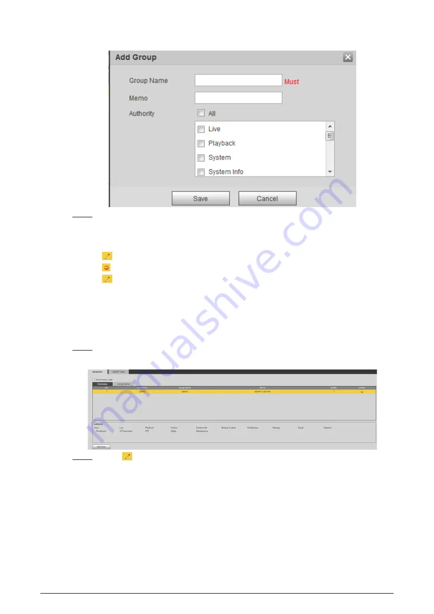
Figure 6-62 Add group 


Step 4 

Click 

Save

The newly added group are displayed in the group name list. 

Related Operations 

  Click 

  to modify group memo or authorities. 

  Click 

  to delete the added group, admin group and user group cannot be deleted. 

  Click 

  in the row of admin group or user group to modify group memo. 

6.5.2.3 Modifying User Password 

For data security, we strongly recommend you change the default password of the Camera and 
modify it regularly, and adopt a complicated and strong password. 
Step 1 

Select 

Setting

 > 

System

 > 

Account

 > 

Account

 > 

Username

Figure 6-63 Username 


Step 2 

Click 

Summary of Contents for D-TPC-BF1241-B3F4-DW-S2

Page 1: ...Thermal Network Camera Web Operation Manual V2 0 1...

Page 2: ...tructions The following signal words might appear in the manual Signal Words Meaning Indicates a high potential hazard which if not avoided will result in death or serious injury Indicates a medium or...

Page 3: ...iance with the manual The manual will be updated according to the latest laws and regulations of related jurisdictions For detailed information see the paper user s manual use our CD ROM scan the QR c...

Page 4: ...de Select Setting Smart Thermal IVS Bold Page names control names specification terms and more Click Add Excluded Area to draw an excluded area on surveillance image Right click to end drawing About t...

Page 5: ...1 Live 14 4 1 1 Introduction to Live Page 14 4 1 2 Function Bar 15 4 1 3 Window Adjustment 16 4 1 3 1 Image Adjustment 16 4 1 3 2 Display of Rule Information 16 4 1 3 3 Optical Axis Calibration 17 4 1...

Page 6: ...38 5 1 6 Configuring Abnormality 39 5 1 6 1 Configuring SD Card Abnormality 39 5 1 6 2 Configuring Network Abnormality 40 5 1 6 3 Configuring Illegal Access 40 5 1 6 4 Configuring Burning Warning 41 5...

Page 7: ...5 6 Configuring Heat Warning 69 5 6 1 Configuring Heat Warning Rule 69 5 6 2 Configuring Smoke and Heat Detection Mode 70 5 7 Configuring Hot Trace 71 5 8 Configuring Pic in Pic 73 5 9 Configuring The...

Page 8: ...k 101 6 2 1 Configuring TCP IP 101 6 2 2 Configuring Port 103 6 2 3 Configuring PPPoE 105 6 2 4 Configuring DDNS 106 6 2 5 Configuring SMTP 107 6 2 6 Configuring UPnP 108 6 2 7 Configuring SNMP 109 6...

Page 9: ...Management 128 6 5 2 1 Adding a User 128 6 5 2 2 Adding a Group 131 6 5 2 3 Modifying User Password 132 6 5 3 Adding ONVIF User 134 6 5 4 Safety Management 134 6 5 4 1 Configuring RTSP Authentication...

Page 10: ...ublic area safety 1 2 Features Safe and stable With a full embedded system this Camera can implement all day monitoring in a stable way A long detection distance Wide monitoring range and long detecti...

Page 11: ...an object Voice intercom For cameras with voice intercom function you can talk indoors with a person near the outdoor monitor to facilitate problem solution Snapshot During live view you can capture a...

Page 12: ...tion of playback function Function Description Manual recording When playing back a video you can record the key information of the video for further check and handling Planned recording After you set...

Page 13: ...lable in visible channel When the Camera detects smoking behavior an alarm is triggered and the system performs linkage actions such as audio alarm white light sending email and recording Boat Detecti...

Page 14: ...settings The alarm is triggered when there is an alarm from external cameras When there is an alarm the system performs linkage actions such as video recording alarm output sending email PTZ operatio...

Page 15: ...ports setting different alarm output conditions to different temperature contrast rules Heat map Supports outputting real time heat map information Then you can do the further analysis through the hea...

Page 16: ...alizing Camera Basic parameters IP address Change IP address according to network planning for the first use or during network adjustment 3 2 Changing IP Address Date time Set date and time to ensure...

Page 17: ...rd well after initialization and modify it regularly Step 1 Open a browser enter the Camera default IP address in the address bar and then press Enter Figure 3 1 Initializing camera Step 2 Set the log...

Page 18: ...change one IP address at one time The chapter uses logging in to web page to change IP addresses as an example Step 1 Log in to the Camera web page Step 2 Select Setting Network TCP IP Figure 3 2 TCP...

Page 19: ...ttings Step 3 Set the network segment of the Camera admin and password Then click Save After the search the system displays the cameras that have been searched The user name and password are both admi...

Page 20: ...configuration PC items Recommended configuration Operation system Windows 7 CPU Intel core i3 Graphics card Intel HD Graphics Storage 2GB Display 1024 768 Resolution Browser Internet Explorer 9 10 11...

Page 21: ...ting Step 1 Open IE browser type the camera IP and then press Enter Figure 3 5 Logging in the Camera Step 2 Click Forgot Password Figure 3 6 Reset the password 1 2 Step 3 Reset the password Scan the Q...

Page 22: ...or wait 24 hours to get a new one Step 4 Click Next Figure 3 7 Resetting the password 2 2 Step 5 Enter a new password and confirm it The password is made up of characters for 8 32 digits and the passw...

Page 23: ...el Double click an image channel and the image channel is displayed in a full video display area Double click the image channel again and the channel will be displayed in a full screen Right click the...

Page 24: ...2 Function Bar 5 Adjustment bar of video window Supports adjusting clarity of video images displaying intelligent rules zooming with focusing at the same time checking real time reports See 4 1 3 Win...

Page 25: ...htness Adjusts the overall image brightness change the value when the image is too bright or too dark The bright and dark areas have equal changes Contrast Change the value when the image brightness i...

Page 26: ...me This function is available on Cameras with the temperature measurement function Prerequisites You have configured the temperature measurement rules For detailed operation see 5 2 5 1 Configuring Te...

Page 27: ...d by sparks from high voltage discharge Mind the distance during laser ranging Less than 50 m will result in a damaged laser Laser ranging does not perform well to those objects such as glass and marb...

Page 28: ...address configured on the PTZ otherwise the Camera cannot control the PTZ Baud rate Configure camera baud rate Data bit It is 8 by default Stop bit It is 1 by default Parity It is None by default Step...

Page 29: ...an The Camera scans on the horizontal direction between the left and right borders Step 1 Click the PTZ tab and select Scan in the PTZ function setting list Step 2 Click Set Figure 4 9 Scan Step 3 Set...

Page 30: ...et number and then click Delete Preset to delete preset it in the tour group Step 6 Enter a tour number Click Start to start touring click Stop to stop it 4 2 2 4 Configuring Pattern Pattern means a r...

Page 31: ...g on Wiper Step 1 Click the PTZ tab and select Wiper in the PTZ Function setting list Figure 4 12 Wiper Step 2 Click Enable to enable the wiper click Disable to disable it 4 2 3 Operating PTZ The corr...

Page 32: ...Z function For detailed operations of PTZ see 4 2 2 Configuring PTZ Functions 4 3 Playback This section introduces playback related functions and operations including video playback and picture playba...

Page 33: ...d It is enabled by default Rules Info is valid only when you enabled the rule during recording 2 Sound Controls the sound during playback Mute mode Vocal state You can adjust the sound 3 Play control...

Page 34: ...e configured storage path 7 Playback video You can select the file type data source and record date 8 Video clip Clip a certain recorded video and save it For details see 4 3 4 Clipping Video 9 Time f...

Page 35: ...system plays the recorded video of the selected date in the order of time Click any point in the colored area on the progress bar The playback starts from that moment Figure 4 18 Progress bar Click t...

Page 36: ...b Step 2 Click the video files of the selected date are listed Step 3 Select dav or mp4 in Download Format If you select dav the rule information can be displayed when playing back the video Step 4 Cl...

Page 37: ...the Record Type drop down list and SD card from the Data Src drop down list Select jpg from Record Type drop down list when playing back pictures and you do not need to select data source Step 3 Click...

Page 38: ...e in the SD card is lower than the configured percentage You have enabled detection to lack of SD card storage space For details see 5 1 6 1 Configuring SD Card Abnormality Disk error An alarm is trig...

Page 39: ...rules an alarm is triggered You have enabled temperature alarm For detailed operations see 5 2 5 1 Configuring Temperature Measuring Rules Temperature difference alarm When temperature difference sat...

Page 40: ...ign disappears If you are on the Alarm page when the selected alarm is triggered there will be detailed alarm information displayed at the right side of the page Step 4 Select the Play Alarm Tone chec...

Page 41: ...the parameters of alarm linkage Figure 5 1 Alarm linkage Table 5 1 Description of alarm linkage parameters Parameter Description Relay in Select the external alarm device Period Set arming periods For...

Page 42: ...m will automatically send an email to users Email linkage takes effect only when SMTP is configured For details see 6 2 7 Configuring SNMP Audio The system broadcasts alarm audio file when an alarm ev...

Page 43: ...configured period Step 1 Click Setting next to Period Figure 5 2 Period Step 2 Set arming periods Alarms will be triggered in the time period in green on the timeline Method one Directly press and dra...

Page 44: ...e the system performs an alarm linkage 5 1 3 1 Configuring Motion Detection When the moving object appears on the image and its moving speed reaches the preset sensitivity the Camera performs an alarm...

Page 45: ...video image is the effective area for Motion Detection by default The red line in the waveform indicates that the Motion Detection is triggered and the green one indicates that there is no motion dete...

Page 46: ...elect the Enable Input Abnormal checkbox and the alarm is triggered when the system detects abnormal sound input Intensity change Select the Enable Intensity Change checkbox and then set Sensitivity a...

Page 47: ...ave 5 1 5 Configuring Temperature Alarm When the temperature meets the defined alarm condition an alarm is triggered and the Camera performs alarm linkage Prerequisites You have configured the tempera...

Page 48: ...udes SD card network illegal access burning warning high humidity alarm and security exception The No SD Card SD Card Error and Capacity Warning events are available only on models that support SD car...

Page 49: ...Abnormality Network Step 2 Select the event type from the Event Type drop down list and then select the Enable checkbox to enable the network detection function Figure 5 9 Network Step 3 Set alarm lin...

Page 50: ...dels Step 1 Select Setting Event Abnormality Burning Warning Step 2 Select the Enable checkbox Step 3 Configure Sensitivity and Energy Threshold Figure 5 11 Burning warning Table 5 2 Description of bu...

Page 51: ...ctions For details see 5 1 1 Alarm Linkage Step 5 Click Save 5 1 6 6 Configuring Security Exception When a hostile attack is detected the Camera performs alarm linkage Step 1 Select Setting Event Abno...

Page 52: ...use the Camera including indoor scenario outdoor scenario and adaptive scenario You can select a scenario as needed and configure and check the scenario Step 1 Select Setting Camera Conditions Conditi...

Page 53: ...n bright and dark areas and the smaller the less If the value is set too large the dark area would be too dark and bright area easier to get overexposed The picture might be hazy if the value is set t...

Page 54: ...a of the visible channel and the thermal channel and displays the image in warm color Cold Color Combines the data of the visible channel and the thermal channel and displays the image in cold color F...

Page 55: ...ode are contained FFC Settings FFC Mode Method of correcting the shutter Auto According to the switch period that you have configured the shutter will be corrected regularly Manual Correct the shutter...

Page 56: ...5 1 1 Alarm Linkage Step 5 Click Save 5 2 5 Configuring Temperature Measurement Parameters Configure temperature measurement rules and when alarm conditions are met an alarm will be triggered 5 2 5 1...

Page 57: ...w rules that you need on the surveillance image Right click to end your drawing You can draw 12 rules at most Select a rule that you have drawn and click Redraw Rule Then you can delete the rule and d...

Page 58: ...ture Slope The temperature difference in each minute Ranges from 600 C min to 600 C min You can set this value when you select Alarm Results as Slope Temperature Error Set a temperature error value an...

Page 59: ...ompares minimum temperatures of two rules When one of the two rules refers to a spot both maximum temperature and minimum temperature are actually average temperature Alarm Condition Contains Lower Ma...

Page 60: ...Target Radiation Coefficient Set Radiation coefficient of targets that are shot by this Camera Ranges from 0 5 1 Target Distance Distance from the Camera to targets that are shot Ranges from 0 m 10 0...

Page 61: ...emperature measurement rules See 5 2 5 Configuring Temperature Measurement Parameters for detailed operation This function is available on models with temperature measurement function Procedure Step 1...

Page 62: ...1 1 Alarm Linkage and 5 1 2 Setting Period Step 4 Click Save 5 2 7 Verification After configuration enable Temperature Alarm Prompt and Play Alarm Tone When an alarm is triggered the Camera prompts an...

Page 63: ...m would play the audio file that you have selected when the subscribed alarm events are triggered Click Clear to remove all the alarm information 5 2 8 Isotherm Stands out the temperature range of the...

Page 64: ...es of palettes for displaying different temperatures You can determine which type of palette to use by the color bars in the image Colored palettes All the colors in the selected palette are used to c...

Page 65: ...arms The recommended installation height is 3 m 5 m In the detection area we recommended high point installation rather than low point installation Install the Camera horizontally and firmly to guaran...

Page 66: ...perimeter and then install the Camera on the L pole Figure 5 27 Typical scene 2 When there are obstructions such as trees and vegetation around the perimeter and wire netting on the perimeter install...

Page 67: ...The camera lens might be burnt Wide view and no obstructions The monitoring scene should be with a wide view No obstructions such as trees vegetation and wire netting in the detection area Not suitabl...

Page 68: ...caused Suitable scene No sky in the image The detection area should be with a wide view and no obstructions The background is simple Drawing multiple rule boxes from far to near Suitable 5 3 2 Config...

Page 69: ...cene Tripwire When the target crosses tripwire from the defined motion direction an alarm is triggered and then the system performs configured alarm linkages Scenes with sparse targets and no occlusio...

Page 70: ...type Step 5 Click Draw Rule to draw a rule line in the image Right click to finish drawing After finishing drawing drag the ends of the line to adjust the detection areas Tripwire Draw a detection li...

Page 71: ...r to delete all drawn detection lines Click Copy to all to copy the drawn filter box to other IVS rules Step 7 Configure the parameters Table 5 11 Description of IVS parameters Parameter Description D...

Page 72: ...lick Add Detect Region to draw a detected area on the image Right click to end drawing Click Add Detect Region again to re draw 2 Click Add Exclude Region to draw an excluded area on the monitoring im...

Page 73: ...nabling it The icon you have selected will be lighted Click the icon again to cancel the smart plan Step 4 Click Save 5 4 3 Configure Call Detection Configure the rule for calling in the visible chann...

Page 74: ...etting the value too large might cause false alarm Step 5 Configure arming periods and alarm linkage action For details see 5 1 1 Alarm Linkage and 5 1 2 Setting Period Step 6 Click Save Result Accord...

Page 75: ...area takes effect only when it has been drawn in the detected area Multiple excluded areas can be drawn in the detected area Step 3 Click Save 5 5 Smoking Detection Configure global rules for smoking...

Page 76: ...5 3 Configure Smoking Detection Configure the rule for smoking detection in the thermal channel When a smoking action is detected an alarm is triggered and the system performs linkages such as recordi...

Page 77: ...se alarm Step 5 Configure arming periods and alarm linkage action For details see 5 1 1 Alarm Linkage and 5 1 2 Setting Period Step 6 Click Save Result According to the configured rules when call acti...

Page 78: ...ea An excluded area takes effect only when it has been drawn in the detected area Multiple excluded areas can be drawn in the detected area Step 3 Click Save 5 6 Configuring Heat Warning Configure the...

Page 79: ...ensitivity and then drag the mouse on the image The higher the sensitivity is the easier a fire will be triggered The whole image is the detection area by default You can draw multiple detection areas...

Page 80: ...he visible channel detects smoke an alarm will be triggered Heat and Smoke When the visible channel detects smoke and the thermal channel detects heat point at the same time an alarm will be triggered...

Page 81: ...emperature an alarm is triggered Select the Cold Spot temperature less than checkbox and when the lowest temperature is smaller than the configured temperature an alarm is triggered If you select both...

Page 82: ...ion Gets temperature of every pixel on thermal images and you can export the heat map Step 1 Select Setting Smart Thermal Thermal Map Acquisition Figure 5 44 Thermal map acquisition Step 2 Configure t...

Page 83: ...l on the PC to obtain the heat map and calculate the temperature of each pixel in the image By analyzing the heat map the functions such as temperature measurement according to the configured rules te...

Page 84: ...the visible image of the Camera and adjust the image parameters to achieve a better image effect Select Setting Camera Conditions Conditions select 1 in Channel and configure the profile For details s...

Page 85: ...he value is the clearer the picture edges will be and if the value is set too big picture noises are more likely to appear Sharpness CNT The bigger the value the stronger the sharpness CNT Gamma Chang...

Page 86: ...tion in Table 6 2 are based on the condition that you have selected Standard as Profile Table 6 2 Description of exposure parameters Parameter Description Anti flicker You can select from 50 Hz 60 Hz...

Page 87: ...value manually to adjust image brightness Iris When selecting Manual or Aperture Priority as the Mode you can configure the iris parameter Exposure Comp When selecting Manual Aperture Priority or Shu...

Page 88: ...tion Backlight Mode Description Off Disable the backlight function BLC The system adjusts exposure according to ambient lighting condition automatically to ensure the clarity of the darkest area WDR T...

Page 89: ...the system auto compensates WB according to color temperature Natural The system auto compensates WB to environments without artificial light to ensure color precision Street Lamp The Camera will impl...

Page 90: ...Mode Then you can configure this parameter You can configure the camera sensitivity for switching between color and black and white mode Delay This configuration is available only when you set Auto in...

Page 91: ...unction is disabled Step 5 Click Save 6 1 1 2 Configuring Thermal Image Configure a specific scenario where you use the Camera including indoor scenario outdoor scenario and adaptive scenario You can...

Page 92: ...ed scene Or you can select the default scene and set the display of the thermal image Low Dynamic Thermal images will be displayed based on the configuration of low dynamic scene High Dynamic Thermal...

Page 93: ...ange is similar to that of Midday but its brightness is lower than Midday Amber It s mainly represented as brown Brighter when the temperature is higher Boulder Color is concentrated on the range of p...

Page 94: ...Sharpness Change the sharpness of image edges The larger the value the more obvious the image edge Do not make the value too large to prevent image noise DDE Makes the details of the image clear The...

Page 95: ...the data of the visible channel and the thermal channel and displays the image in cold color Fusion Rate It ranges from 0 to 100 The larger the value the larger the proportion of the visible channel...

Page 96: ...od of correcting the shutter Auto According to the switch period that you have configured the shutter will be corrected regularly Manual Correct the shutter by yourself FFC Period You can configure th...

Page 97: ...Profile Management When configuring the profile management you can select from Normal Full Time and Schedule Step 1 Select Setting Camera Conditions Profile Management Step 2 Select the channel Select...

Page 98: ...based on time Step 4 Click Save 6 1 2 Configuring Video Parameters 6 1 2 1 Configuring Video Streaming Configure video stream parameters such as compression resolution frame rate bit rate type bit rat...

Page 99: ...the FPS is the clearer and smoother the video will be Bit Rate Type You can select bit rate type Fixed the bit rate changes little and keeps close to the configured bit rate value Changeable the bit r...

Page 100: ...The default value is 1 which means no layered coding Watermark Settings Select the checkbox to enable watermark Then you can check if the video has been tampered by verifying the watermark Watermark c...

Page 101: ...ure measurement information Step 4 Click Save 6 1 2 3 Configuring Video Overlay Configure overlay information and it will be displayed on the Live page 6 1 2 3 1 Configuring Privacy Masking You can en...

Page 102: ...ay Step 2 Select the channel Select 1 in Channel to configure the parameters for the visible channel Select 2 in Channel to configure the parameters for the thermal channel Step 3 Click Channel Title...

Page 103: ...time is displayed on the video image Step 5 Click Week Display and then the week information is displayed on the video image You can drag the Time Title box on the video image with your mouse to adjus...

Page 104: ...location of the box Step 5 Click Save 6 1 2 3 5 Configuring Font You can adjust size and color of the font on the video images based on your own needs Step 1 Select Setting Camera Video Overlay Step 2...

Page 105: ...checkbox You will be informed that OSD information is to be closed Click Save Step 5 Click Upload Picture and select a picture The picture is displayed in video images You can drag the Picture Overla...

Page 106: ...Configuring ROI Select ROI in the image and then the selected image would display with configured quality Step 1 Select Setting Camera Video ROI Step 2 Select the channel Select 1 in Channel to confi...

Page 107: ...orage path Step 2 Click Browse and configure storage paths of live snapshot live record playback snapshot playback download video clips and heat map Table 6 11 Storage path description Path Descriptio...

Page 108: ...o clips refer to the clipped video of playback page C Users admin WebDownload LiveSnapshot is the default path Heat Map Heat map comes from the location Setting Temperature C Users admin WebDownload L...

Page 109: ...eam or Sub Stream then only video images are transmitted Encode Mode You can select audio encode mode G 711A G 711Mu and AAC are included The configured audio encode mode applies to audio and intercom...

Page 110: ...ion is available on select models Step 3 Click Save 6 2 Configuring Network 6 2 1 Configuring TCP IP You can configure IP address DNS Domain Name System server and so more according to network plannin...

Page 111: ...the DHCP takes effect or not MAC Address Host s MAC address cannot be modified IP Version Select IPv4 or IPv6 IP Address Enter the IP address and subnet mask according to your own needs All the IPv6...

Page 112: ...ping packet A demonstration of configuring IP address with ARP Ping To obtain a free IP address you need to ensure that the Camera and your PC are in the same LAN Get MAC address from the Camera label...

Page 113: ...he maximum number of users web client platform client or mobile phone client that can connect to the Camera simultaneously the value is 10 by default TCP Port Port of transmission control protocol The...

Page 114: ...pe 0 HTTPS Port Real Time Messaging Protocol The port that RTMP provides service It is 1935 by default HTTPS Port HTTPS communication port It is 443 by default 5000 Port The service port for Windows X...

Page 115: ...e same domain name no matter how the IP address changes Prerequisites Check the DNS server types that the Camera supports Third party server might collect your device information after DDNS is enabled...

Page 116: ...the DDNS service provides website Password Update period The update cycle of the connection between your Camera and the server 10 minutes are set by default Step 3 Click Save Open your browser and ty...

Page 117: ...alth Mail The system sends test mail to check if the connection is successfully configured Click the checkbox and configure the Sending Interval and then the system sends test mail as the set interval...

Page 118: ...gure 6 30 UPnP Step 4 Click Save Type http external network IP address external port number to access Cameras in Intranet whose ports correspond to your router 6 2 7 Configuring SNMP SNMP Simple Netwo...

Page 119: ...server Using V1 and V2 might cause data leakage and V3 is recommended Step 3 In Trap Address enter the IP address of the PC that has MIB Builder and MG SOFT MIB Browser installed and leave other param...

Page 120: ...tep 4 Click Save Result View device configuration through MIB Builder or MG SOFT MIB Browser 1 Run MIB Builder and MG SOFT MIB Browser 2 Compile the two MIB files with MIB Builder 3 Load the generated...

Page 121: ...P 224 0 1 0 238 255 255 255 for the Camera and adopt the multicast protocol Procedure Step 1 Select Setting Network Multicast Figure 6 34 Multicast Step 2 Select the channel Select 1 in Channel to con...

Page 122: ...Step 1 Select Setting Network Auto Register Step 2 Select the Enable checkbox Step 3 Set auto registration parameters Figure 6 35 Auto registration Table 6 20 Auto registration parameter description P...

Page 123: ...o assure bandwidth reduce transmission delay packet loss rate and delay jitter to improve experience 0 63 means 64 degrees of priority 0 for the lowest and 63 the highest Step 1 Select Setting Network...

Page 124: ...status shows online The information of the IP address MAC address device name and device SN will be collected The collected information is for remote access only You can cancel the Enable selection t...

Page 125: ...party platform such as Ali and YouTube to realize video live view RTMP can be configured by admin only RTMP supports the H 264 H 264 B and H 264H video formats and the AAC audio format only Step 1 Se...

Page 126: ...me period according to the Record Delay setting To use the record linkage function set record plan for motion detection alarm and enable auto recording in record control 6 3 1 Configuring Schedule 6 3...

Page 127: ...le days at one time You can set 6 time periods per day Step 4 Click Save 6 3 1 2 Configuring Snapshot Plan According to the configured snapshot plan the system enables or disables snapshot at correspo...

Page 128: ...rectly press and drag the left mouse button to set time period for normal snapshot on the timeline Figure 6 43 Snapshot Method two Enter an actual time period 1 Click Setting next to a day Figure 6 44...

Page 129: ...apshot Plan Step 1 Select Setting Storage Schedule Holiday Schedule Step 2 Select from record and snapshot Step 3 Select days that you need and then set them as the holiday Those days with yellow colo...

Page 130: ...age Destination Local Click Read Only and then the SD card is set to read only Click Read Write and then the SD card is set to read write Click Hot Swap and then you can pull out the SD card Click Ref...

Page 131: ...er Emergency Local Select the Emergency Local checkbox and when the FTP server does not work all the files are saved to the internal SD card Step 4 Click Save Click Test to check whether the server ha...

Page 132: ...the video in advance of a triggered alarm event For example if the pre event record is set to be 5 s the system saves the recorded video of 5 s before the alarm is triggered When an alarm or motion de...

Page 133: ...e the best image display effect under night vision condition Step 3 Click Save 6 4 2 Configuring Wiper Step 1 Select Setting Peripheral Wiper Figure 6 52 Wiper Step 2 Configure the running mode Timing...

Page 134: ...e fan works automatically Manual Select the Enable checkbox to manually start the fan Step 4 Click Save 6 4 4 Configuring Heater Step 1 Select Setting Peripheral Heater Figure 6 54 Heater Step 2 Selec...

Page 135: ...l Table 6 28 General parameter description Parameter Description Name The name of the Camera Each Camera has a unique name Language Select the system language Video Standard Select video standard from...

Page 136: ...ime of DST with dates or days of the week NTP When you need the Camera to transmit its time to NTP server you can select the NTP checkbox to enable it Server IP address or domain name of the NTP serve...

Page 137: ...t included Administrator users can modify all the uses password You can have 19 users and 8 groups at most You can manage users through single user or group duplicate user names or group names are not...

Page 138: ...129 Figure 6 58 User settings Step 3 Configure parameters Figure 6 59 Add user operation permission...

Page 139: ...rameter Description Username User s unique identification You cannot use existing user name Password Enter password and confirm it The two items must be the same Confirm Password Group name The group...

Page 140: ...segment Enter the start address and end address of the host to be added 2 Enable Validity Period and then set the start time and end time 3 Enable Period and then click Time to set the period that al...

Page 141: ...roup admin group and user group cannot be deleted Click in the row of admin group or user group to modify group memo 6 5 2 3 Modifying User Password For data security we strongly recommend you change...

Page 142: ...133 Figure 6 64 Modify user 1 Step 3 Select the Modify Password checkbox Figure 6 65 Modify user 2...

Page 143: ...tep 1 Select Setting System Account ONVIF User Step 2 Click Add User Figure 6 66 ONVIF user Step 3 Enter the username password confirm the password and then select group name Figure 6 67 Add user Step...

Page 144: ...Figure 6 69 System service Step 2 Enable functions on the System Service page Table 6 31 System service parameters description Parameter Description SSH It is disabled by default SSH Secure Shell can...

Page 145: ...ou enable this function ensure that the matching Cameras or software can decode audio and video that you have encoded Transmission of audio and video between your Camera and the third party platform c...

Page 146: ...Certificate creating For uploading the authenticated certificate click Browse to select the certificate and certificate key click Upload to upload them and then skip to Step5 Step 3 Enter the required...

Page 147: ...138 Figure 6 72 Install a certificate Step 5 Click Download to download root certificate Step 6 Click Download Root Certificate Figure 6 73 File download Step 7 Click Open...

Page 148: ...139 Figure 6 74 Certificate information 1 Step 8 Click Install Certificate Figure 6 75 Certificate information 2 Step 9 Click Next...

Page 149: ...ure 6 76 Certificate import wizard 1 Step 10 Select the storage location and click Next Figure 6 77 Certificate import wizard 2 Step 11 Click Finish and a dialog box showing The import was successful...

Page 150: ...PING prohibited Enable the PING prohibited function and the Camera will not respond to the ping request Prevent Semijoin Enable the Prevent Semijoin function and the Camera can provide service normall...

Page 151: ...gment to be added MAC address Enter MAC address of the host to be added All IP addresses Set all IP addresses in allowlist or restricted list Device All Ports Set access ports You can select all ports...

Page 152: ...System Auto Maintain Step 2 Configure auto maintain parameters Select the Auto Reboot checkbox and set the reboot time the system automatically restarts as the set time every week Select the Auto Dele...

Page 153: ...ce to default configuration or factory setting Step 1 Select Setting System Default Figure 7 2 Default setting Step 2 Restore the Camera to default setting Click Default and all the configurations exc...

Page 154: ...otice 2 If there is any upgrade available click Upgrade and then the system starts upgrading Click Manual Check to check for upgrade manually 7 5 Information You can view the information including ver...

Page 155: ...ing group deleting group and modifying group Safety Includes password resetting and IP filter Step 3 Click Search Click a certain log and then you can view the detailed information in Detailed Informa...

Page 156: ...147 Select Setting Information Online User Figure 7 7 Online user...

Page 157: ...cabinet and implement well done access control permission and key management to prevent unauthorized personnel from carrying out physical contacts such as damaging hardware unauthorized connection of...

Page 158: ...s we suggest that you check online users regularly to see if the device is logged in without authorization Check device log By viewing the logs you can know the IP addresses that were used to log in t...

Reviews: