47
Leave a sufficient distance when cutting the tubes.
Achtung
Achtung
2. Get ready to install the Water Filter
1) Measure an approximate distance between the filter and the
Water Tube and cut the tube off filter vertically.
2) Connect the tubes to the filter as the figure shows.
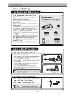
How to install Water Line
WATER SUPPY KIT
1. The water pressure should be 3kgf/cm
2
or more to run the
automatic icemaker.
Checkup your tap water pressure ; if a cup of 180cc is full
within 10 seconds, the pressure is OK.
2. When installing the water tubes, ensure they are not colse to
any hot surfaces.
3. The water filter only filters water ; it does not eliminate any
bacteria or microbes.
4. If the water pressure is not so high to run the icemaker, call the
local plumber to get an additional water pressure pump.
5. The filter life depends on the amount of use. We recommend
you replace the filter at least once every 6months.
When attaching the filter, place it for easy access (removing
& replacing)
6. After installation of refrigerator and water line system, select
[WATER] on your control panel and press it for 2~3 minutes to
supply water into the water tank and dispense water.
7. Use sealing tape to every connection of pipes/tubes to ensure
there is no water leak.
8. The water tube should be connected to the cold water line.
Check the parts below for installing water supply.
Some other necessary parts are available at your local
service agents.
Installation Procedure
1. Join Connector to the tap water line
2. How to install water line
Place the rubber washer inside the tap connector and
screw onto the water tap.
Achtung
Achtung
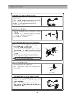
1) First lock the main tap water valve.
Check if connector B and C has its own rubber packing ring in it.
2) Join Connector-C to the water tap, then Connector -B to
connector -C with a wrench or spanner.
3) Insert water pipe into Connector-B and join Connector-A with a
wrench or spanner.
4) In case Connector-C does not fit water tap join Connector-B
directly to the tap.(See Figure B.)
If no connector fits water tap, call your local service.
5) Unlock main tap water valve, open tap water and check if any
water leaks on each joins.
3011202000
(3010541600)
(A:3019503200
B:3019503300)
(3012020700)
Connector A,B,C
(7112401211)
<Figure A>
<Figure B>
(3014454510)
INSTALLATION GUIDE
Summary of Contents for FRS-T20DA Series
Page 3: ...2 1 EXTERNAL SIZE FRS T20DA EXTERNAL VIEWS ...
Page 4: ...3 FRS T20FA EXTERNAL VIEWS ...
Page 6: ...5 3 Cold Air Circulation Freezer Compartment Refrigerator Compartment EXTERNAL VIEWS ...
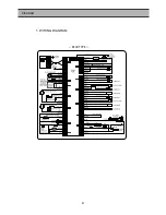
Page 42: ...41 RSCR TYPE 1 WIRING DIAGRAM DIAGRAM ...
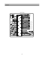
Page 43: ...42 DIAGRAM CSR TYPE ...
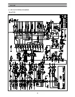
Page 44: ...43 DIAGRAM 2 CIRCUIT WIRING DIAGRAM Main PCB ...
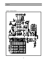
Page 45: ...44 FRONT PCB DIAGRRAM DIAGRAM ...
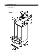
Page 52: ...CABINET 51 EXPLODED VIEW 1 FRS T20DA ...
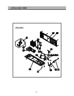
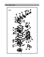
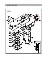
Page 53: ...EXPLODED VIEW MECH ROOM 52 ...
Page 54: ...EXPLODED VIEW R Room 53 ...
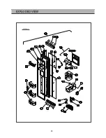
Page 55: ...54 EXPLODED VIEW F ROOM ...
Page 56: ...55 EXPLODED VIEW F Door ...
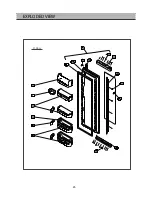
Page 57: ...56 EXPLODED VIEW R Door ...
Page 64: ...CABINET 63 EXPLODED VIEW 3 FRS T20FA ...
Page 65: ...EXPLODED VIEW MECH ROOM 64 ...
Page 66: ...EXPLODED VIEW R Room 65 ...
Page 67: ...66 EXPLODED VIEW F ROOM ...
Page 68: ...67 EXPLODED VIEW F Door ...
Page 69: ...68 EXPLODED VIEW R Door ...

