background image

30

OPERATION AND FUNCTIONS


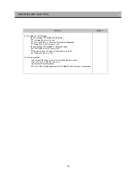
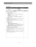
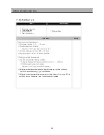
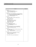
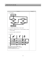
9) "EI" ERROR 
     

  Cause : I-SENSOR disconnection / short 


  Control : After water suppy, Ice drop every 4.8hour. 


  Termination : When I-SENSOR is normal. 

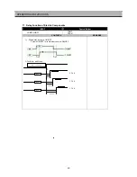
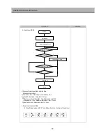
10) "EF" Error 
     

  Cause : When Flow-sensor is ERROR(There is no Pulse during some time.) 


The number of pulse signal is below 10 by 1 sec during water supply.


  Control : 

 by time (By

Control

 Vector time recorded EEPROM.) 

                (Generally, Water is supplied about 5.5s.) 

Termination : Exchange Flow-Sensor


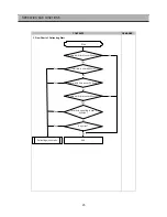
11) "E9" Error 
     

  Cause : I-Sensor temp(5min after Water supply) doesn't go up.


  Control : Normal control 


 Termination : Normal condition 

     
12) "ES" Error (Micro S/W  Error)
     

  Cause : When it senses 1min continuously

.   


  Control : Stop Dispenser & Crusher function. 


  Display : Relative LED  is  flicker. 


 Termination : Normal condition 

 
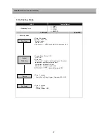
13) Malfunction of Ice Drop Motor   
     

  Cause : Malfunction of Ice Drop Motor. 

[ Check the Motor by pushing Test S/W.] 


  Termination : Exchange Motor   

 
14) "Eu" Error 

Cause :  Switch(which senses if the ice is full or not) is in Error. 

  Control : When dropping the Ice, the motor just rotates 90 degree. 
  Termination : When the switch is in normal.


15) "EA" Error 
     

  Cause : When sensing Ice dropping by time 3times in level sensor SW Error.


  Control :Stop of Ice Maker. 


  Termination : With normal level switch.

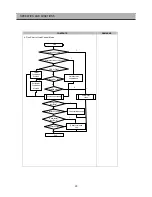
                  * Reinput of power or push of icemaker test switch.


  * When all ERROR CODE is normal, the Refrigerator reset. 


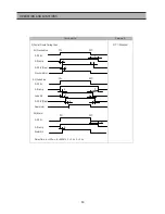
16) "Et" ERROR
     

  Cause : Level switch error (No pulse is sensed for some time.)


  Control : By time. ( Supply mode is skipped.)


  Te rmination : Normal condition.


CONTENTS

REMARKS

Summary of Contents for FRS-T20DA Series

Page 1: ...l some parts can be changed for improving their performance without notice in the parts list So if you need the latest parts information please refer to PPL Parts Price List in Service Information Center http svc dwe co kr http svc dwe co kr ...

Page 2: ...Parts List 69 7 Defrosting cycle 8 Defrosting mode 9 Error display 10 11 Forced Initial defrosting 12 13 Buzzer LCD Background light 14 15 16 Explanation after delivery Prevention of Comp restart Back up function 17 Delay function 34 35 35 18 19 20 Home bar heater Control of interior lights Demo function 21 Reg of R sensor off point 22 Summary C O N T E N T S SAFETY AND PRECAUTION 1 For starters b...

Page 3: ...2 1 EXTERNAL SIZE FRS T20DA EXTERNAL VIEWS ...

Page 4: ...3 FRS T20FA EXTERNAL VIEWS ...

Page 5: ... Welding Points 5 35 7 points 5 point Flow of Refrigeration Cycle Compressor High Pipe Conn B Wire Con Pipe F Hot Pipe Hot Pipe Conn R Hot Pipe Dryer Capillary Tube Low Evaporator Accumulator Suction Pipe Pipe Suction Conn EXTERNAL VIEWS ...

Page 6: ...5 3 Cold Air Circulation Freezer Compartment Refrigerator Compartment EXTERNAL VIEWS ...

Page 7: ... Ice cubes storage case 7 Dairy pocket 14 Refrigerator pocket 15 Refrigerator case 5 Freezer pocket 6 Freezer case 11 Chilled case 12 Refrigerator shelve 13 Movable Egg case 2 Freezer light 8 Deordorizer 9 Refrigerator light A 10 Wine holder 3 Water Ice Dispenser 4 Freezer shelve 4 NAME OF EACH PART ...

Page 8: ...Movable Egg case 14 Refrigerator pocket 5 Freezer pocket 11 Chilled case 6 Freezer case 12 Refrigerator shelve 3 Water Ice Dispenser 9 Refrigerator light A 4 Freezer shelve 10 Wine holder 7 Dairy pocket Freezer Refrigerator Compartment 2 Freezer light 8 Deordorizer 1 Ice cubes storage case EXTERNAL VIEWS ...

Page 9: ... Automatic Start Stop 190 EXTERNAL DIMENSION mm COOLING CONTROL SYSTEM 513 928 803 1808 Fin Evaporator Forced Fan Cooling System NET WEIGHT kg CONTENTS FRS T20DA FRS T20FA MODEL NAME DIVISION 127 129 174 365 556 191 ISO Storage Volume L ISO Gross Volume L FREEZER REFRIGERATOR TOTAL SPECIFICATIONS 1 SPECIFICATIONS ...

Page 10: ...REFRIGERANT R134a VOLTAGE V HZ 100 50 60 110 60 115 120 60 127 60 220 60 220 240 50 230 50 X 3016400100 X 3016400100 X X X RATED VOLTAGE X 200V X 200V X X X RATED CAPACITANCE X 100 X 100 X X X 4 RUNNING CAPACITOR REFRIGERANT R134a VOLTAGE V HZ 100 50 60 110 60 115 120 60 127 60 220 60 220 240 50 230 50 X 400EL15130 X X 3016401170 3016401920 3016401170 RATED VOLTAGE X 230V X X 350V 400V 350V RATED ...

Page 11: ...0 3012811100 PART CODE TYPE NAME PART CODE SPEC W SPEC W PART CODE 10 LAMP ASSEMBLY REFRIGERANT R134a 100 50 60 110 60 115 120 60 127 60 220 60 220 240 50 230 50 X 120V 15W 240V 15W X 3013600070 3013600060 X 120V 25W 230 240V 25W X 3013602020 3013602010 11 MAIN PCB ASSEMBLY REFRIGERANT R134a VOLTAGE V HZ 100 50 60 110 60 115 120 60 127 60 220 60 220 240 50 230 50 X SBS 2ND PREMIUM X 30143D2060 301...

Page 12: ...LENOID CRUSHER REFRIGERANT R134a VOLTAGE V HZ 100 50 60 110 60 115 120 60 127 60 220 60 220 240 50 230 50 x 110 127V 60Hz 220 240V 50 60Hz x 3015402900 3015402000 17 VALVE WATER REFRIGERANT R134a VOLTAGE V HZ 100 50 60 110 60 115 120 60 127 60 220 60 220 240 50 230 50 x 110 127V 60Hz 220 240V 50 60Hz x 3015402800 3015402200 SPEC PART CODE SPEC PART CODE SPEC PART CODE SPEC PART CODE 13 THERMOSTAT ...

Page 13: ...17101 KP 30 For America El Salvador 4 401PD17101 KP 211 For Japan Taiwan 5 3011300801 BP 3PIN 6 3011303010 267 For Chile 7 3011315310 For Israel 8 3011303050 BS 1363A For U K Middle Asia Singapore Malaysia 9 3011301200 KP 551 550 For China Australia Upper power cord s part code is only lead wire without any kinds of terminal or houisng SPECIFICATIONS 12 ...

Page 14: ...t Color Type NOBLESS SILVER NEO WHITE LUXURY MIRROR CHERRY WOOD THE OTHERS Color Code NAH4A NHH4G LMH4G CWH4W THE OTHERS Part Code 3000054340 3000054320 3000054300 3000054330 3000054310 2 Assembly Refrigerator Door FRS T20FA 100 127V Blowing Agent Color Type NOBLESS SILVER NEO WHITE LUXURY MIRROR CHERRY WOOD THE OTHERS Color Code NAH4A NHH4G LMH4G CWH4W THE OTHERS Part Code 300003944A 300003941A 3...

Page 15: ...ce Initial mode Water 6 Other display modes Normal Operation Silent Mode CUSTOM LCD Normal Mode Load Mode Silence Mode Sleep Mode Freezer Refrigerator BAR DIAL DIAL Temp SEG DIAL DIAL 1 Letters of FRZ REF HIGH SET TEMP FUZZY DEODO SILENT SLEEP WATER LOW 2 Icons of FUZZY DEODO SLEEP Water 3 Temp bars and lines ON ON SILENT icon OFF OFF ON ON ON ON ON OFF SPEED letters OFF ON ON OFF OFF SPEED bars O...

Page 16: ...ed at Soft Mid and Mid Strong modes Just temperatures and bars are shown Temperature progress Low Low Mid Mid Mid High HIgh Temp indication 4 3 2 1 0 5 SUPER REF button When this mode is chosen QUICK icon and letters of refrigerator flicker 6 times and ON The set temperature and bars are still the previous value 6 SLEEP button Start by pushing the button ON lights Stop by pushing button again OFF ...

Page 17: ...ater Icon Box is always ON Stop by pushing ICE MAKER LOCK button again ICE MAKER LOCK Icon is OFF The Icon Box of Cube Ice Crushed Ice is OFF Water Icon Box is ON 10 Filter information The normal OK Icon is on for 6 month after first power input After six month CHANGE Icon is on How to reset Filter information Push LOCK button and push the ICE MAKER LOCK button for 3 seconds ...

Page 18: ...F point 20 0 If RT 13 F S OFF point is 2 UP Freezer Middle OFF point 18 4 Freezer Compartment Low Mid HIgh High DIFF 4 degrees 5 Control point of each mode Temp MODE ON point OFF point Low Mid High STEP DIFF STEP DIFF ON OFF DIFF 1 8 0 2 0 0 2 4 0 2 6 0 1 4 0 1 6 0 2 2 0 1 8 0 1 6 0 2 0 0 Low Mid Mid High Low Low Mid Mid Mid High High C C C C C Low Mid Mid Mid High DIFF 2 degrees respectively 2 Te...

Page 19: ...fan are controlled by ON OFF point of each mode 3 Refrigerator Compartment ON OFF Refreigerator Compartment middle OFF point 0 7 If RT 13 R S OFF point is 2 UP Refrigerator Middle OFF point 2 7 4 Refrigerator Compartment Low 5 Prevention of weak poor refrigeration 1 When weak refrigeration is sensed comp is ON regardless of F sensor 2 When R sensor reaches R fan OFF point comp is controlled by F s...

Page 20: ... 7 6 7 5 7 8 7 9 7 7 Super refrigeration proceeds for 40 minutes Example of temperature change Refrigerator Low normal Super refrigeration 1 R fan and comp are ON until R sensor reaches to over refrigeration OFF point 7 2 After reaching to the point it goes on with HIGH mode until the end of Super refrigeration It returns to normal after Quick refrigeration of 40 minutes C C C C C C C C C C C C C ...

Page 21: ...rmination of Sleep mode 1 MODE 1 F sensor 9 In case of F sensor error When other button is pushed during this mode Total F R door open time exceeds 30 seconds during the mode If Sleep mode is terminated by and F R fan delay for 5 minutes and restart of this mode is prevented for 40minutes If it exceeds time limit of 130 minute Mode1 is terminated and Mode2 starts 2 MODE 2 Sleep mode is terminated ...

Page 22: ...ght below 5 7 Lux optical sensor surface Standard value to decide daytime above 4 16 Lux optical sensor surface 3 Control Method Control Mode F FAN R FAN C FAN Normal Silence Load Control 12V 12V 10V 10V 10V 12V 4 Termination Condition The mode stops if lux value is above the standard for more than 1 minute 6 Control of Each Mode INPUT Control Object 1 CDS SENSOR 2 R SENSOR 3 F SENSOR 1 F FAN 14V ...

Page 23: ... cool Heater defrosting Pause Defrosting cycle After door opening the load control enters if the condition complies with During Sleep Mode1 load control isn t active 5 Control Method 5 1 Control mode by F R door open time over 30 seconds F R fan works by 14V respectively 5 2 Control mode by F sensor On Point 5 degree F fan works by 14V 5 3 Control mode by R sensor On Point 5 degree R fan works by ...

Page 24: ...trol mode Silence Control Door F S F Fan R S R Fan Door Open 30sec after open Load Mode Start Ref Load Stop Frz Load Stop On 5deg On 5deg Frz Overload Input Frz Load Start Frz Stop Condition after 20min 20min 20min Ref Load 12V 12V 10V 8V 3 Start stop of load control mode Normal defrosting control F S F Fan R S R Fan D efro stin g S ta rt C o n d itio n to s ta rt L o ad M ode bu t avoide d bu rin...

Page 25: ...erload of both compartments Y N Freezer Compartment Overload Refrigerator Compartment Overload Y N Y N F load control over 20min F sensor OFF point Overload mode control Overload mode Normal mode control N F load control mode stop R sensor OFF point R load control mode stop End Load control is avoided N Y R load control over 20 min Y Y Y N Y N N Y N ...

Page 26: ... 4 Any error mode R1 F1 D1 F3 RT S Door switch 2 Conditions to start defrosting mode 1 The mode starts with the following conditions Anyerror happens when total comp work time is 6 or 8 or 24hours Total door open time is over 3 minutes Any door F or R open time is over 3 minutes 2 Defrosting mode starts unconditionally as long as total comp work time is 24 hours even if the above conditions are no...

Page 27: ...Defrosting Start Start Comp work time is over 24 hours Total time is over 60 hours Comp work time is over 6 hours Any error End Defrosting mode starts Yes Yes Yes Yes No No No No Comp work time is over 2 hours Total door open time is over 3 minutes Yes Yes No No ...

Page 28: ... 3 If F sensor 27 then PRE COOL becomes OFF 1 Comp F fan R fan OFF HTR ON 2 Time limit 30 seconds Heater is ON regardless of D sensor temperature right after defrosting start 30 minutes in case of D1 Error 80 minutes in normal control state Heater Defrosting is OFF 1 Time 7 minutes Comp F fan R fan Heater Homebar HTR OFF 1 Time 5 minutes Comp ON F R fan Heater OFF Pre Cool Heater Defrosting Pause ...

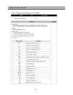
Page 29: ...eset if they turn to be normal 5 Error Code ERROR CODE CONTENTS F1 r1 F sensor disconnection short R sensor disconnection short rt RT sensor disconnection short D sensor disconnection short dr d1 R Door Switch defective dF F Door Switch defective dH Homebar Refreshment Center Door Switch defective C1 Cycle abnormal or defective F3 E1 EF Et Return after defrosting abnormal or defective I senser def...

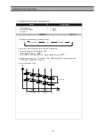
Page 30: ...tion of function related door switch sensing If door switch open close is sensed the error is terminated automatically 6 C1 ERROR Cause in case comp works for over 3 hours when D sensor temp is over 5 Control Normal operation When D sensor temp is below 5 in comp OFF it is terminated 7 F3 ERROR Cause in case defrosting return is done by time limit of 80min Control Deletion of Pre cool mode in defr...

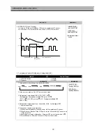
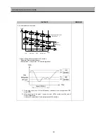
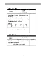
Page 31: ...ly Control Stop Dispenser Crusher function Display Relative LED is flicker Termination Normal condition 13 Malfunction of Ice Drop Motor Cause Malfunction of Ice Drop Motor Check the Motor by pushing Test S W Termination Exchange Motor 14 Eu Error Cause Switch which senses if the ice is full or not is in Error Control When dropping the Ice the motor just rotates 90 degree Termination When the swit...

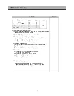
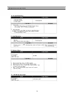
Page 32: ...plugin Defrosting Mode CONTENTS REMARKS If D sensor temp 3 5 defrosting mode starts from Pre cool at first power input Comp is delayed for 6 min at the initial defrosting 12 Buzzer or Alarm INPUT Control Object F PCB buttons Door Switch Initial Power Input BUZZER CONTENTS REMARKS 1 Buzzer sounds if any button of F PCB is pushed 2 Buzzer sounds 4 times 3 seconds after initial power input 3 Buzzer s...

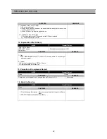
Page 33: ... Object FRZ SET button REF SET button Power Cord Electrical components and LCD CONTENTS REMARKS 1 Start Push REFRIGERATOR SET button for 3 seconds within 10 seconds just after power input 2 Control 1 Electrical components are OFF for 3 hours 2 Display operates in normal way 15 Prevention of Compressor Restart INPUT Control Object None Comp CONTENTS REMARKS Comp does not start again for 6 minutes t...

Page 34: ...MP ON OFF COMP F FAN CONTENTS REMARKS 1 F fan delay by comp ON OFF F fan is ON OFF 1 minute after comp is ON OFF 2 F an Delay and Priority R F A N O N c o ndi tio n 0 5s ec O N O N O N 1 0s ec 1 5s ec F FA N C F A N O F F O F F O F F 1 min 1 min OPERATION AND FUNCTIONS ...

Page 35: ... Home Bar Models Only door opening R lights turn ON for 1 minute after sensing HOME BAR switch open If the switch is pushed again within 1 minute the light turns on another 1 minute 4 DISPENSER LAMP CONTROL DISPENSER LAMP turns ON OFF by DISPENSER SW Dispenser Lamp turns ON for 5 seconds after sensing switch close 20 Demonstration Function INPUT Control Object LOCK button REFRIGERATOR SET button S...

Page 36: ...set water filter REF SET SLEEP 5 times DEMO function INPUT Control Object Resistance of R sensor Mid ON OFF Point CONTENTS REMARKS Regulation of R sensor OFF point 1 5degree DOWN In case refrigeration of refrigerator is weak or insufficient take the following action R SENSOR R36 R37 R38 R36 R SENSOR standard resistance in normal mode 31 4K R37 In case of weak ref cut J1 to down the standard resist...

Page 37: ...e tray turns to be horizontal and ice making mode starts 3 Control of water hose heater 4 Water supply stand by 5 Crusher Function Heater is always ON if RT sensor has an error or RT is below 15 degree Heater is always ON for 60 minutes max limit time if Flow sensor has an error Condition if ice is sensed full Operation proceeds to Ice making mode Ice separating and water supply modes stop Termina...

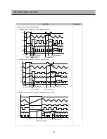
Page 38: ...ns 9 5 below continuously Ice maker comlpete 2 Ice Drop MODE status Ice tray level level normal level 8 11 Max 1 1 8 5 12 2 0 2 10 11 1 1 1 Each Section s Time used in S W ERROR Confirm 2 Ice Drop MOTOR Rotation is Sensible by Each Sections 3 S W ERROR Ice Drop Every Time 4 Ice Drop MOTOR ERROR Stop to the Status START 130 min passed I S 12 5 ICE Drop mode I S 9 5 15 min passed C C C C C Start ICE...

Page 39: ... A S Steps Water input by Time Maximum Water Inut Time 15 sec 4 RT S 7 13 19 29 39 39 I S 10 9 8 7 6 5 Flow Sensor Normal Operation Flow Pulse Value sets 238 Flow Sensor error Water input time 5 5 sec C C C C C C C C C C C C Water Input Confirm MODE I S Temp Rising Value with RT S Temp Mode after 5 min Estimate of Water Input 1 Sec passed after inlet value on Water input pulse 10 Water input pulse...

Page 40: ...ar Water Icon Box is always ON Stop by pushing Lock Ice Maker button again Lock Icer Maker Icon is OFF The Icon Box of Cube Ice Crushed Ice is OFF Water Icon Box is ON 3 Display Initial Mode Water ICON Letter is ON A rectangle Line around the icon lights up to indicate your selection is on The Icon of water Ice Cube Crushed Ice is always ON Exception Dispenser S W Error When pushing Lock Ice Maker...

Page 41: ...1 Crushed Ice D P SW D P Lamp D P S V Flap Crusher Motor D P SW D P Lamp Cube S V D P S V Flap Gear Motor D P SW D P Lamp Water S V Delay Time A 500ms B 500Ms C 2 0s D 5 0s D A A C 3 2 Cubed Ice A C A B D 3 3 Water D A 40 A OPERATION AND FUNCTIONS ...

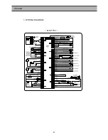
Page 42: ...41 RSCR TYPE 1 WIRING DIAGRAM DIAGRAM ...

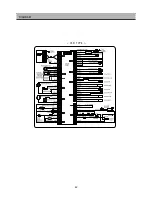
Page 43: ...42 DIAGRAM CSR TYPE ...

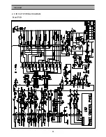
Page 44: ...43 DIAGRAM 2 CIRCUIT WIRING DIAGRAM Main PCB ...

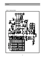
Page 45: ...44 FRONT PCB DIAGRRAM DIAGRAM ...

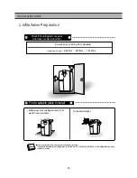
Page 46: ...d direct sunlight Once the installation place is ready follow the installation instructions If surround temperature of refrigerator is low below 5 foods can be frozen or the refrigerator can work in abnormal way Check if the refrigerator can pass a doorway or enter a door first Find a suitable place to install 1 Installation Preparation INSTALLATION GUIDE ...

Page 47: ...thewater linewhenremovingthedoor 2 Turn top hinge fastener counterclockwise 3 4 times Disconnect harness wires 1Unscrew top hinge cover with a screw driver Insert a thin screw driver into the side groove of the cover to remove 3 Lift up the front of hinge to remove After the hinge is removed the door can fall down forward Be careful 4Lift the door straight up to remove 2Unscrew top hinge cover wit...

Page 48: ...select WATER on your control panel and press it for 2 3 minutes to supply water into the water tank and dispense water 7 Use sealing tape to every connection of pipes tubes to ensure there is no water leak 8 The water tube should be connected to the cold water line Check the parts below for installing water supply Some other necessary parts are available at your local service agents Installation P...

Page 49: ...r and attach it 2 Insert the filter box into the holder 1 Fasten the Water Tube with the Fastener A 2 Check if the tube is bent or sqeezed If so set it right to prevent any water leak FastenerA WaterTube 3 Remove any substances in the filter 1 Open the main tap water valve and check if water comes out of the Water Tube 2 Check if the Water Valve is open in case water does not come out 3 Leave the ...

Page 50: ...n front to the top hole of door 4 Turn the hinge fastener tightly to the end Connect harness wirings and screw ground wire 5 Insert the water tube far into the coupling 2Let the top of door close to the cabinet and insert the top hinge pin to the top hole of freezer door Insert the back of hinge to the groove of protrusion first then front to the top hole of door 1Insert the bottom hole of refrige...

Page 51: ...nsert a hexagonal wrench into the groove of adjusting nut and turn clockwise until the door is level 4Once the door is balanced fasten the hinge bolts tightly and screw the front cover 2 Loosen 3 hinge bolts 2 on the left 1 on the right a little Do not unfasten them completely Insert a hexagonal wrench into the groove of adjusting nut and turn clockwise until the door is level 1Insert a screw driv...

Page 52: ...CABINET 51 EXPLODED VIEW 1 FRS T20DA ...

Page 53: ...EXPLODED VIEW MECH ROOM 52 ...

Page 54: ...EXPLODED VIEW R Room 53 ...

Page 55: ...54 EXPLODED VIEW F ROOM ...

Page 56: ...55 EXPLODED VIEW F Door ...

Page 57: ...56 EXPLODED VIEW R Door ...

Page 58: ...PING 1 T1 TRS 4 x 12 MFZN 17 3013223400 HOSE ICE MAKER TUBE AS 1 18 3012519200 GUIDE CAB W TUBE A AS 1 19 3011485600 COVER GUIDE CAB W TUBE A 1 HIPS 20 3011202000 CLAMP WATER TUBE A 5 PA 66 21 3012907300 HINGE U R AS 1 PO T5 0 22 3012907200 HINGE U L AS 1 PO T5 0 25 3016001240 SPECIAL BOLT T 8 6 x 22 SWCH22A YL 26 3015306700 SUPPORTER U HI AS 2 PO T5 0 27 3012104400 FOOT ADJUST AS 2 28 3010654500 ...

Page 59: ...0 MOTOR C FAN AS 1 DC12V 2 5W 51 3011802200 FAN 1 ABS O D 3 17 x D110 52 3011200500 CLAMP FAN 1 SUS 304 53 3016806900 DRYER AS 1 XH 9 15g 54 3011474730 COVER MACHROOM AS 1 SBHG T0 4 55 7112401211 SCREW TAPPING 6 T1 TRS 4 x 12 MFZN 56 VALVE WATER AS 1 57 3012007800 FIXTURE MOTOR A 1 PP 58 3015911400 MOTER R FAN AS 1 59 3012007900 FIXTURE MOTOR B 1 HIPS 60 7122401211 SCREW TAPPING 2 T2S TRS 4 x 12 M...

Page 60: ...03200 CAP SCREW 2 PE 87 3018124000 SWITCH LAMP 1 SP201R 7DR 88 3017100500 FLAP MULT DUCT 1 PP 89 3013345000 INSU MULT DUCT AS 1 F PS 90 3011472750 COVER MULT DUCT 1 HIPS 91 3013408100 KNOB MULT DUCT 1 ABS 92 3017905310 SOCKET R LAMP AS 1 250V 1A 93 LAMP R B 1 94 3015508000 WINDOW R LAMP B 1 MIPS 95 3011473000 COVER SENS 1 ABS 96 3014805400 SENSOR R AS 1 PBN 438 97 3011171330 CASE EGG AS 1 GPPS 98 ...

Page 61: ...GUIDE ICE CRUSHER R 1 ABS 122 3012520500 GUIDE ICE CRUSHER L 1 ABS 123 3014559510 PLATE LAMP F 1 SBHG T0 8 124 3017905200 SOCKET F LAMP AS 2 125 LAMP F 2 126 7121300811 SCREW TAPPING 4 T2S PAN 3X8 MFZN 127 7112401211 SCREW TAPPING 4 T1 TRS 4 x 12 MFZN 128 3015507710 WINDOW F LAMP 1 MIPS 129 3016002710 SPECIAL SCREW 2 4 x 12 131 3018124000 SWITCH LAMP 1 SP201R 7DR 132 3017827120 SHELF F A AS 3 GLAS...

Page 62: ...152 1 3011437000 COVER DISPNS BOX 1 ABS SPRAY 3015509300 WINDOW F PCB AS 1 OTHER COLOR 152 2 3015509310 WINDOW F PCB AS 1 BK MIRROR 152 3 30143C4110 PCB F AS 1 152 4 3016303400 BUTTON CONTL 8 ABS AL 152 5 3012307800 GASKET BUTN 1 NR 152 6 7173300811 SCREW TAPPTITE 7 TT2 BIN 3X8 MFZN 153 3010542200 BOX DISPNS ICE SHUT AS 1 154 3015102200 SPRING ICE D LEVER 1 Ø0 9 SUS 304 155 3011485900 COVER ICE FL...

Page 63: ...T690DG 170 3012201800 FRAEM R DR O 1 AL 171 3016040200 SPECIAL SCREW FRAME 4 4X14 S18C 172 3012604500 HANDLE INTR DR AS 1 173 3016040200 SPECIAL SCREW FRAME 4 4X14 S18C 174 3010930500 CAP R INTR DR T 1 ABS SPRAY 175 7142401211 SCREW TAPPING 7 T2 TRS 4X14 MFZN 176 3010964400 CAP R INTR DR U AS 1 ABS SPRAY 177 7142401211 SCREW TAPPING 7 T2 TRS 4X14 MFZN 178 PANEL R DR 1 190 SENSOR D AS 1 PBN 43 191 ...

Page 64: ...CABINET 63 EXPLODED VIEW 3 FRS T20FA ...

Page 65: ...EXPLODED VIEW MECH ROOM 64 ...

Page 66: ...EXPLODED VIEW R Room 65 ...

Page 67: ...66 EXPLODED VIEW F ROOM ...

Page 68: ...67 EXPLODED VIEW F Door ...

Page 69: ...68 EXPLODED VIEW R Door ...

Page 70: ...PING 1 T1 TRS 4 x 12 MFZN 17 3013223400 HOSE ICE MAKER TUBE AS 1 18 3012519200 GUIDE CAB W TUBE A AS 1 19 3011485600 COVER GUIDE CAB W TUBE A 1 HIPS 20 3011202000 CLAMP WATER TUBE A 5 PA 66 21 3012907300 HINGE U R AS 1 PO T5 0 22 3012907200 HINGE U L AS 1 PO T5 0 25 3016001240 SPECIAL BOLT T 8 6 x 22 SWCH22A YL 26 3015306700 SUPPORTER U HI AS 2 PO T5 0 27 3012104400 FOOT ADJUST AS 2 28 3010654500 ...

Page 71: ...0 MOTOR C FAN AS 1 DC12V 2 5W 51 3011802200 FAN 1 ABS O D 3 17 x D110 52 3011200500 CLAMP FAN 1 SUS 304 53 3016806900 DRYER AS 1 XH 9 15g 54 3011474730 COVER MACHROOM AS 1 SBHG T0 4 55 7112401211 SCREW TAPPING 6 T1 TRS 4 x 12 MFZN 56 VALVE WATER AS 1 57 3012007800 FIXTURE MOTOR A 1 PP 58 3015911400 MOTER R FAN AS 1 59 3012007900 FIXTURE MOTOR B 1 HIPS 60 7122401211 SCREW TAPPING 2 T2S TRS 4 x 12 M...

Page 72: ...03200 CAP SCREW 2 PE 87 3018124000 SWITCH LAMP 1 SP201R 7DR 88 3017100500 FLAP MULT DUCT 1 PP 89 3013345000 INSU MULT DUCT AS 1 F PS 90 3011472750 COVER MULT DUCT 1 HIPS 91 3013408100 KNOB MULT DUCT 1 ABS 92 3017905310 SOCKET R LAMP AS 1 250V 1A 93 LAMP R B 1 94 3015508000 WINDOW R LAMP B 1 MIPS 95 3011473000 COVER SENS 1 ABS 96 3014805400 SENSOR R AS 1 PBN 438 97 3011171330 CASE EGG AS 1 GPPS 98 ...

Page 73: ...E ICE CRUSHER L 1 ABS 123 3014559510 PLATE LAMP F 1 SBHG T0 8 124 3017905200 SOCKET F LAMP AS 2 125 LAMP F 2 126 7121300811 SCREW TAPPING 4 T2S PAN 3X8 MFZN 127 7112401211 SCREW TAPPING 4 T1 TRS 4 x 12 MFZN 128 3015507710 WINDOW F LAMP 1 MIPS 129 3016002710 SPECIAL SCREW 2 4 x 12 131 3018124000 SWITCH LAMP 1 SP201R 7DR 132 3017827120 SHELF F A AS 3 GLASS HIPS 133 3011171460 CASE F A AS 1 GPPS HIPS...

Page 74: ...152 1 3011437000 COVER DISPNS BOX 1 ABS SPRAY 3015509300 WINDOW F PCB AS 1 OTHER COLOR 152 2 3015509310 WINDOW F PCB AS 1 BK MIRROR 152 3 30143C4110 PCB F AS 1 152 4 3016303400 BUTTON CONTL 8 ABS AL 152 5 3012307800 GASKET BUTN 1 NR 152 6 7173300811 SCREW TAPPTITE 7 TT2 BIN 3X8 MFZN 153 3010542200 BOX DISPNS ICE SHUT AS 1 154 3015102200 SPRING ICE D LEVER 1 Ø0 9 SUS 304 155 3011485900 COVER ICE FL...

Page 75: ...SCREW C 8 SUS M5 1 7 1 9 3010951500 CAP HOMEBAR ARM PLT L 2 ABS 171 10 3016030800 SPECIAL SCREW A 2 SUS M5 171 11 3016030600 SPECIAL SCREW C 4 SUS M5 171 12 3014567100 PLATE HOMEBAR ARM R AS 1 STS 304 171 13 3017754300 DOOR HOMEBAR URT AS 1 171 14 3014537000 PLATE HOMEBAR ARM L AS 1 STS 304 172 3012201800 FRAME R DR O 1 AL 173 3016040200 SPECIAL SCREW FRAME 4 4X14 S18C 174 3012604500 HANDLE INTR D...

Reviews: