Power Train
Testing And Adjusting
Install Carrier Assembly
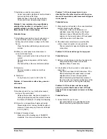
(5) Bearing cap (6) Bolts
3.
Put the carrier assembly in position in the housing
assembly. Install bearing caps (5) and four bolts
(6).
Tighten bolts (6) to a torque of 220
L
25 N¥m
(160
L
18 lb¥ft).
4.
Install lockwashers (7) and locknuts (8). Use
tooling (A) to check gear clearance (backlash)
between bevel gear (2) and pinion (9). Adjust
locknuts (8) until the clearance is 0.15 to 0.20 mm
(0.006 to 0.008 in.).
Adjust the clearance by turning one locknut (8) in
and the other locknut out an equal amount.
5.
Check the rolling torque again as shown in Pinion
Bearing Adjustment, Step 6. Tighten locknuts (8)
equally to preload the differential case bearings.
Proper bearing preload will increase the rolling
torque at the pinion (recorded in Pinion Bearing
Adjustment, Step 6) by 0.63 to 0.88 N¥m (5.6 to
7.8 lb¥in).
6.
Measure backlash again. After backlash and
preload are correct, bend a tab on each
lockwasher (7) into a slot in locknuts (8) to hold
them in position.
Correct Tooth Contact Setting
7.
Check the tooth contact pattern as follows. Check
the tooth contact setting between the bevel gear
and pinion after the gear clearance (backlash) and
bearing preload adjustments have been made as
follows.
a.
Put a small amount of Prussian blue, red lead or
paint on the bevel gear teeth. Turn the pinion in
both directions and check the marks made on the
bevel gear teeth.
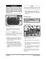
Short Toe Contact Setting
b.
With no load, correct tooth contact setting will be
as shown. The area of contact starts near the toe
of the gear and goes 30 to 50% up the length of
the tooth.
With this setting, when a load is put on the gear,
the load will be over the correct area of the teeth.
26


