


ENGLISH
80
4.3.1.2.1 Automatic
alignment of sensitive parameters
When a multi inverter system is detected, the unit checks for consistency of the set parameters. If the
sensitive parameters are not aligned on all inverters, the display of each inverter shows a message
requesting whether to transfer the configuration of the specific inverter to the entire system. On acceptance,
the sensitive parameters on the inverter where confirmation is given are distributed to all other inverters in
the series.
If there are configurations incompatible with the system, the configuration cannot be aligned from these
inverters.
During normal operation, modification of a sensitive parameter on an inverter will cause automatic alignment
of the parameter on all other inverters without any request for confirmation.
NOTE:
Automatic alignment of sensitive parameters has no effect on all other types of parameter
.
In the particular case of inserting an inverter with default settings in the series (in the case of an inverter
which replaces an existing model or an inverter with restored factory settings), if the configurations applied,
with the exception of factory settings, are consistent, the inverter with the factory settings will automatically
take on the sensitive parameters of the series.
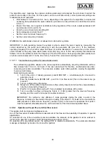
4.3.1.3
Parameters with optional alignment
These are the parameters that are admissible even if not aligned with other inverters. Each time these
parameters are modified, when SET or MODE is pressed, the request is displayed whether to modify the
entire communicating inverter series. In this way if the series has all the same settings, the same data does
not need to be set on all inverters.
List of parameters with optional alignment:
LA
Language
RC
Rated
current
FN
Rated
frequency
MS
Measurement
system
FS
Maximum
frequency
FL
Minimum
frequency
SO
Dry running factor
AC
Acceleration
AE
Antiblocking
O1
Output 1 function
O2
Output 2 function
4.4 Multi-inverter
settings
When a multi inverter system is switched on, the addresses are assigned automatically and, by means of an
algorithm, an inverter is nominated as the settings leader. The leader decides on the frequency and order of
start-up of each inverter in the series.
The settings mode is sequential (inverters start one at a time). When start-up conditions are enabled, the first
inverter starts, and when this reaches maximum frequency, the next one starts, and so on. The order of start-
up is not necessarily ascending according to the machine address, but depends on the hours of operation;
see ET: Tempo di scambio par. 6.6.9.
When the minimum frequency FL is used, and there is only one inverter operative pressure surges may
occur. Depending on the case, pressure surges may be inevitable and may occur at the minimum frequency
when this value, in relation to the hydraulic load, causes a pressure level greater than the required value. On
multi inverter systems, this problem remains limited to the first pump that is started up, as on the subsequent
pumps the situation is as follows: when the previous pump reaches the maximum frequency, the next one
starts up at the minimum frequency to then reach the maximum frequency. When the frequency of the pump
Summary of Contents for MCE-22/P
Page 278: ...274 1 276 2 279 3 280 4 282 5 283 6 4 20 284 7 285 8 286 9 287 10 290 11 290 12 292...
Page 279: ...275 IEC 60634...
Page 280: ...276 1 6 MCE 22 P MCE 15 P MCE 11 P 1 1 1...
Page 282: ...278 2 5 2 1 2 1 2 2 1 1 2 1 2 L L L 2 2 4 15...
Page 283: ...279 2 2 2 1 2 2 1 1 3 1 LN 2 2 3 1 3 4 4...
Page 284: ...280 A 3 3 2 2 1 2 4 3 1 UVW 2 2 4 3 50 60 200 1...
Page 286: ...282 4 2 2 3 Press e Flow 5 A B C D d1 d2...
Page 291: ...287 3 9 64 X 128 4 MODE SET 9 7 MODE 1 SET 8 3 EEprom SET 6 SET MODE...
Page 292: ...288 3 1 9 3 2 1 2 3 2 1 MODE SET MODE 8 2 2 5 5 5 2 2 9...
Page 294: ...290 3 2 2 10 SET 10 15 12 11...
Page 296: ...292 12 12 12 GO SB...
Page 297: ...293 4 4 1 Link 8 4 2 4 2 1 Link 2 Link 5...
Page 300: ...296 4 3 1 2 1 4 3 1 3 SET MODE LA RC FN MS FS FL AC AE O1 1 O2 2 4 4 ET 6 6 9 FL...
Page 326: ...322 BL 10 6 24 24 30 LP 180 200 HP OT TE 100 C 85 C OB BT 120 C 100 C OC 10 6 OF 10 6 30...
Page 327: ...323 8 8 1 PMW 4 2 8 2 8 3 8 3 SET EE EEprom FLASH...
Page 494: ...490 1 492 2 495 3 496 4 498 5 499 6 4 20 mA 500 7 501 8 502 9 503 10 506 11 506 12 508 13 523...
Page 495: ...491 IEC 364 inverter...
Page 496: ...492 1 Inverter inverter inverter 6 inverter MCE 22 P MCE 15 P MCE 11 P 1 1 1...
Page 499: ...495 2 2 2 1 inverter inverter 2 2 1 1 inverter 3 1 LN 2 inverter 2 PVC 3 inverter 1 3 inverter...
Page 502: ...498 4 2 2 3 Press Flow 5 A B C D d1 d2...
Page 507: ...503 3 9 oled 64 X 128 4 MODE SET 9 inverter 7 MODE 1 SET 8 3 EEprom SET 6 SET MODE...
Page 508: ...504 3 1 9 3 2 1 2 3 2 1 MODE SET Setpoint MODE 9 ONOMA TOY MENOY 2 Setpoint 2 5 5 5 2 2 9...
Page 512: ...508 12 12 12 GO SB FAULT...
Page 543: ...539 8 8 1 PMW 4 2 8 2 inverter 8 3 8 3 inverter SET EEPROM FLASH setpoint...
Page 599: ...595...