


ENGLISH
96
Incorrect settings of the parameters RC and FN, or improper connections can generate the errors "OC", "OF" and
in the case of operation without the flow sensor, may generate the false errors "BL". Incorrect settings of the
parameters RC and FN can also cause failure of the current sensitivity protection device, leading to loads
exceeding the safety threshold of the motor, with consequent damage to the latter.
Incorrect configuration of the electric motor with star or delta connection may cause damage to the motor.
Incorrect configuration of the operating frequency of the electric pump can cause damage to the latter.
5.1.3
Setting the direction of rotation
Once the pump has started up, the user must ensure that the direction of rotation is correct (the direction is usually indicated by
an arrow on the pump casing). To start up the motor and check the direction of rotation, simply switch on a utility.
From the same menu as RC (MODE SET – "Installer menu") press MODE and scroll through the menus to RT. In these conditions,
b and – enable the user to invert the direction of motor rotation. The function is also enabled when the motor is running.
If it is not possible to see the direction of motor rotation, proceed as follows:
Method to check rotation frequency
-
Access parameter RT as described above.
-
Turn on a utility and observe the frequency that is shown on the status bar at the bottom of the utility control page, to ensure that the
operating frequency is less than the rated frequency of the pump FN.
-
Without changing collection, modify parameter RT by means of b or – and check frequency FR again.
-
The correct RT parameter is that which requires, compared to collection, a lower frequency FR.
5.1.4
Setting the setpoint pressure
From the main menu, press and hold MODE and SET simultaneously until “SP” appears on display. In these conditions, buttons
“+” and “–“ enable respectively increase and decrease of the required pressure value.
The regulation range depends on the sensor used.
Press SET to return to the main page.
5.1.5
System with flow sensor
From the installer menu (the same used to set RC, RT and FN) scroll through the parameters using MODE to reach FI.
To work with the flow sensor set FI to 1. Use MODE to scroll through to the next parameter FD (pipeline diameter) and set the
diameter in inches of the pipe mounting the flow sensor.
Press SET to return to the main page.
5.1.6
System without flow sensor
From the installer menu (the same used to set RC RT and FN) scroll through the parameters using MODE to display FI. To work
without the flow sensor, set FI to 0 (default value).
Without the flow sensor, there are two flow reading modes, both settable on parameter FZ in the installer menu.
•
Automatic (self-learning): the system automatically identifies the flow and automatically adjusts settings accordingly. To
set this operating mode, set FZ to 0.
•
Minimum frequency mode: in this mode the shutdown frequency is set at zero flow. To use this mode, move to parameter
FZ, close delivery gradually (to avoid generating overpressure) and read the frequency value at which the inverter is
stabilised. Set FZ at this value + 2.
Example: if the inverter stabilises at 35Hz, set FZ at 37.
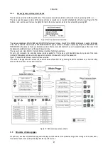
Summary of Contents for MCE-150/P
Page 308: ...306 IEC 60634 1...
Page 309: ...307 1 6 1 1...
Page 312: ...310 1 2 1 1 1 1 2 5 2 1 2 1 2...
Page 313: ...311 2 1 1 2 1 2 L L L 2 2 4 2 15 2 2 1 1a...
Page 314: ...312 2a 3a 4b 1b 127 240 240 480...
Page 318: ...316 GP GI 6 6 4 6 6 5 7 A B C D...
Page 323: ...321 50 60 7 DC AC 50 60 8 6 2 1 5 36 36 12 3 3 3 3 2 13 9 10 8...
Page 325: ...323 I1 F1 I1 6 6 13 2 I2 P2 6 6 13 3 I3 F3 6 6 13 4 I4 1 F4 6 6 13 5 10 GND 7 I1 I2 I3 I4...
Page 326: ...324 3 13 64 X 128 4 MODE SET 11 SET 9 MODE 1 SET 11 3 EEprom SET 6 SET MODE 3 1 11...
Page 327: ...325 3 2 1 2 3 2 1 MODE SET MODE 10 2 2 5 5 5 2 2 12...
Page 329: ...327 12 SET 14 15 13 15 3 3...
Page 331: ...329 15 14 3 4 PW 6 6 16 GO SB...
Page 332: ...330 4 4 1 Link 8 4 2 4 2 1 Link Link 15...
Page 333: ...331 17 Link 4 2 2 0 5V 4 20 A 0 4 2 2 1 FI FI 4 2 2 2 FZ 6 5 9 1 4 2 2 3 0 5 4 20 A 0 5 0...
Page 336: ...334 4 4 2 2 4 2 5 4 5 ET 6 6 9 FL 4 5 1 4 5 1 1 ET ET ET ET 0 ET 6 6 9 4 5 1 2 23 23...
Page 339: ...337 FZ FZ 2 35 FZ 37 FZ FZ FZ FZ FI 0 FZ FZ 0 5 1 7 6 GI GP FL TB...
Page 362: ...360 OC 10 6 OF 10 6 33 8 8 1 PMW 4 2 8 2 8 3 8 3 SET EE EEprom FLASH...
Page 548: ...546 IEC 364 1 inverter...
Page 549: ...547 1 Inverter inverter inverter 6 inverter 1 1...
Page 552: ...550 1 2 1 1 inverter inverter 1 1 2 5 inverter inverter 2 1 inverter inverter 2 1 2 C...
Page 554: ...552 2a 3a 4b...
Page 558: ...556 GP GI 6 6 4 6 6 5 inverter 7 A B C D...
Page 567: ...565 3 2 1 2 3 2 1 MODE SET Setpoint MODE 10 ONOMA TOY MENOY 2 Setpoint 2 5 5 5 2 2 12...
Page 571: ...569 15 15 14 3 4 Password inverter password password inverter password PW 6 6 16 GO SB FAULT...
Page 728: ...726 IEC 364 1 1...
Page 729: ...727 1 1...
Page 732: ...730 1 2 1 1 1 2 5 2 1 2 1 2 C...
Page 733: ...731 2 1 1 0 2 1 2 L L L 2 2 4 2 15 2 2 1 1...
Page 734: ...732 2a 3a 4b...
Page 738: ...736 GP GI 6 6 4 6 6 5 7 2 2 3 2 Press Flow 6 A B C D...
Page 743: ...741 DC AC 50 60 Hz 7 DC V AC 50 60 Hz Vrms V 8 6 V 2 1 5 V 36 36 12V A 3 3 3 3 2 13 8 10 8...
Page 744: ...742 12 J5 I1 11 17 16 18 16 17 I2 11 15 16 18 15 16 I3 11 14 13 18 13 14 I4 11 12 13 8 12 13 9...
Page 746: ...744 3 13 Oled 64 X 128 4 MODE SET 11 SET or 9 MODE 1 SET 10 3 EEprom SET SET or MODE...
Page 751: ...749 14 14 3 4 PW 6 6 16 GO SB FAULT...
Page 752: ...750 4 4 1 Link 8 4 2 4 2 1 Link Link 15...
Page 966: ...964 IEC 60634 1...
Page 967: ...965 1 6 1 1...
Page 970: ...968 1 2 5 2 1 2 1 2 2 1 1...
Page 971: ...969 2 1 2 L L L 2 2 4 2 15 2 2 1 1a 1a...
Page 976: ...974 3 2 2 3 2 Press Flow 6 A B C D...
Page 981: ...979 50 60 7 DC AC 50 60 8 6 2 1 5 36 36 12 3 3 3 3 2 13 2 10 8...
Page 982: ...980 5 J5 I1 11 17 16 18 16 17 I2 11 15 16 18 15 16 I3 11 14 13 18 13 14 I4 11 12 13 8 12 13 8...
Page 984: ...982 SET 9 3 EEprom SET 6 SET MODE 3 1 11 3 2 1 2 3 2 1 MODE SET MODE 10 2 2 5 5...
Page 986: ...984 4 3 2 2 12 SET 7 15 13...
Page 987: ...985 8 3 3 psi 12 GO SB BL LP HP EC...
Page 989: ...987 PW 6 6 16 4 4 1 Link 8 4 2 4 2 1 Link Link 15...
Page 993: ...991 4 4 2 2 4 2 5 4 5 ET 6 6 9 FL 4 5 1 4 5 1 1 ET ET ET ET 0 ET 6 6 9 4 5 1 2 23 23...
Page 1020: ......
Page 1021: ......
Page 1022: ......
Page 1023: ......


