


ENGLISH
75
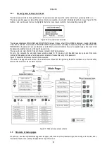
Figure 6: Pump connection MCE 22/P – MCE 15/P – MCE 11/P
Incorrect connection of the earthing line, to a terminal other than the earth terminal can cause irremediable
damage to the equipment.
Incorrect connection of the power line on the output load terminals can cause irremediable damage to the
equipment.
Cable section in mm²
10 m
20 m
30 m
40 m
50 m
60 m
70 m
80 m
90 m
100 m
120 m
140 m
160 m
180 m
200 m
4 A
1,5
1,5
1,5
1,5
1,5
1,5
1,5
1,5
2,5
2,5
2,5
2,5
4
4
4
8 A
1,5
1,5
1,5
1,5
2,5
2,5
2,5
4
4
4
6
6
6
10
10
12 A
1,5
1,5
2,5
2,5
4
4
4
6
6
6
10
10
10
10
16
16 A
2,5
2,5
2,5
4
4
6
6
6
10
10
10
10
16
16
16
20 A
2,5
2,5
4
4
6
6
10
10
10
10
16
16
16
16
16
24 A
4
4
4
6
6
10
10
10
10
16
16
16
16
16
16
28 A
6
6
6
6
10
10
10
10
16
16
16
16
16
16
16
32 A
6
6
6
6
10
10
10
16
16
16
16
16
16
16
16
36 A
10
10
10
10
10
10
16
16
16
16
16
16
16
16
16
40 A
10
10
10
10
10
16
16
16
16
16
16
16
16
16
16
44 A
10
10
10
10
10
16
16
16
16
16
16
16
16
16
16
48 A
10
10
10
10
16
16
16
16
16
16
16
16
16
16
16
52 A
16
16
16
16
16
16
16
16
16
16
16
16
16
16
16
56 A
16
16
16
16
16
16
16
16
16
16
16
16
16
16
16
60 A
16
16
16
16
16
16
16
16
16
16
16
16
16
16
16
Table applicable to cables in PVC with 4 wires (3 earth)
Table 6: Section of 4-wire cable (3 earth)
As regards the section of the earthing cable, refer to current standards.
2.2.2
Hydraulic connections
The inverter is connected to the hydraulic section by means of pressure and flow sensors. The pressure sensor is always required,
while the flow sensor is optional if operating in stand alone mode, and is compulsory when creating multi inverter systems.
Both are mounted on pump delivery and connected by means of the relative cables to the respective inputs on the inverter board.
Always fit a check valve on pump suction and an expansion vessel on pump delivery.
In all circuits subject to the risk of water hammer (for example irrigation systems with flow rate interrupted suddenly by solenoid valves),
fit a further check valve downline of the pump and mount the sensors and expansion vessel between the pump and valve.
Summary of Contents for MCE-150/P
Page 308: ...306 IEC 60634 1...
Page 309: ...307 1 6 1 1...
Page 312: ...310 1 2 1 1 1 1 2 5 2 1 2 1 2...
Page 313: ...311 2 1 1 2 1 2 L L L 2 2 4 2 15 2 2 1 1a...
Page 314: ...312 2a 3a 4b 1b 127 240 240 480...
Page 318: ...316 GP GI 6 6 4 6 6 5 7 A B C D...
Page 323: ...321 50 60 7 DC AC 50 60 8 6 2 1 5 36 36 12 3 3 3 3 2 13 9 10 8...
Page 325: ...323 I1 F1 I1 6 6 13 2 I2 P2 6 6 13 3 I3 F3 6 6 13 4 I4 1 F4 6 6 13 5 10 GND 7 I1 I2 I3 I4...
Page 326: ...324 3 13 64 X 128 4 MODE SET 11 SET 9 MODE 1 SET 11 3 EEprom SET 6 SET MODE 3 1 11...
Page 327: ...325 3 2 1 2 3 2 1 MODE SET MODE 10 2 2 5 5 5 2 2 12...
Page 329: ...327 12 SET 14 15 13 15 3 3...
Page 331: ...329 15 14 3 4 PW 6 6 16 GO SB...
Page 332: ...330 4 4 1 Link 8 4 2 4 2 1 Link Link 15...
Page 333: ...331 17 Link 4 2 2 0 5V 4 20 A 0 4 2 2 1 FI FI 4 2 2 2 FZ 6 5 9 1 4 2 2 3 0 5 4 20 A 0 5 0...
Page 336: ...334 4 4 2 2 4 2 5 4 5 ET 6 6 9 FL 4 5 1 4 5 1 1 ET ET ET ET 0 ET 6 6 9 4 5 1 2 23 23...
Page 339: ...337 FZ FZ 2 35 FZ 37 FZ FZ FZ FZ FI 0 FZ FZ 0 5 1 7 6 GI GP FL TB...
Page 362: ...360 OC 10 6 OF 10 6 33 8 8 1 PMW 4 2 8 2 8 3 8 3 SET EE EEprom FLASH...
Page 548: ...546 IEC 364 1 inverter...
Page 549: ...547 1 Inverter inverter inverter 6 inverter 1 1...
Page 552: ...550 1 2 1 1 inverter inverter 1 1 2 5 inverter inverter 2 1 inverter inverter 2 1 2 C...
Page 554: ...552 2a 3a 4b...
Page 558: ...556 GP GI 6 6 4 6 6 5 inverter 7 A B C D...
Page 567: ...565 3 2 1 2 3 2 1 MODE SET Setpoint MODE 10 ONOMA TOY MENOY 2 Setpoint 2 5 5 5 2 2 12...
Page 571: ...569 15 15 14 3 4 Password inverter password password inverter password PW 6 6 16 GO SB FAULT...
Page 728: ...726 IEC 364 1 1...
Page 729: ...727 1 1...
Page 732: ...730 1 2 1 1 1 2 5 2 1 2 1 2 C...
Page 733: ...731 2 1 1 0 2 1 2 L L L 2 2 4 2 15 2 2 1 1...
Page 734: ...732 2a 3a 4b...
Page 738: ...736 GP GI 6 6 4 6 6 5 7 2 2 3 2 Press Flow 6 A B C D...
Page 743: ...741 DC AC 50 60 Hz 7 DC V AC 50 60 Hz Vrms V 8 6 V 2 1 5 V 36 36 12V A 3 3 3 3 2 13 8 10 8...
Page 744: ...742 12 J5 I1 11 17 16 18 16 17 I2 11 15 16 18 15 16 I3 11 14 13 18 13 14 I4 11 12 13 8 12 13 9...
Page 746: ...744 3 13 Oled 64 X 128 4 MODE SET 11 SET or 9 MODE 1 SET 10 3 EEprom SET SET or MODE...
Page 751: ...749 14 14 3 4 PW 6 6 16 GO SB FAULT...
Page 752: ...750 4 4 1 Link 8 4 2 4 2 1 Link Link 15...
Page 966: ...964 IEC 60634 1...
Page 967: ...965 1 6 1 1...
Page 970: ...968 1 2 5 2 1 2 1 2 2 1 1...
Page 971: ...969 2 1 2 L L L 2 2 4 2 15 2 2 1 1a 1a...
Page 976: ...974 3 2 2 3 2 Press Flow 6 A B C D...
Page 981: ...979 50 60 7 DC AC 50 60 8 6 2 1 5 36 36 12 3 3 3 3 2 13 2 10 8...
Page 982: ...980 5 J5 I1 11 17 16 18 16 17 I2 11 15 16 18 15 16 I3 11 14 13 18 13 14 I4 11 12 13 8 12 13 8...
Page 984: ...982 SET 9 3 EEprom SET 6 SET MODE 3 1 11 3 2 1 2 3 2 1 MODE SET MODE 10 2 2 5 5...
Page 986: ...984 4 3 2 2 12 SET 7 15 13...
Page 987: ...985 8 3 3 psi 12 GO SB BL LP HP EC...
Page 989: ...987 PW 6 6 16 4 4 1 Link 8 4 2 4 2 1 Link Link 15...
Page 993: ...991 4 4 2 2 4 2 5 4 5 ET 6 6 9 FL 4 5 1 4 5 1 1 ET ET ET ET 0 ET 6 6 9 4 5 1 2 23 23...
Page 1020: ......
Page 1021: ......
Page 1022: ......
Page 1023: ......


