


ENGLISH
98
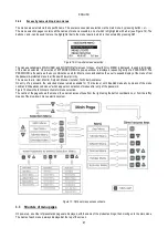
5.2
Troubleshooting on initial installation
Fault
Possible causes
Remedy
The display shows
EC
Pump current (RC) not set
Set parameter RC (see section 6.5.1).
The display shows
BL
1) No water.
2) Pump not primed.
3) Flow sensor disconnected.
4) Entry of setpoint too high for pump.
5) Inverted direction of rotation.
6) Incorrect setting of pump current RC(*).
7) Maximum frequency too low (*).
8) SO parameter not set
correctly
9) MP minimum pressure parameter
not set correctly
1-2) Prime the pump ad ensure that there is no air in the pipelines. Check that intake or any
filters are not obstructed Check that the pipeline from the pump to the inverter is not damaged
or leaking.
3) Check the connections to the flow sensor.
4) Lower the setpoint or use a pump suited to system requirements.
5) Check the direction of rotation (see 6.5.2).
6) Set a correct value for pump current RC(*) (see 6.5.1).
7) If possible, increase FS or lower RC(*) (see 6.6.6).
8) set SO value correctly (see para. 6.5.14)
9) set MP value correctly (see para. 6.5.15
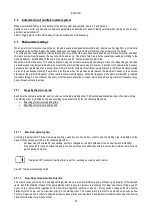
The display shows
BPx
1) Pressure sensor disconnected.
2) Pressure sensor faulty.
1) Check the pressure sensor cable connection.
BP1 refers to the sensor connected to Press 1, BP2 to press2,
BP3 to current sensor connected to J5
2) Replace the pressure sensor.
The display shows
OF
1) Excessive absorption.
2) Pump blocked.
3) Pump absorbs high current on start-up.
1) Check type of connection; star or delta. Check that the motor does not absorb current over
the max. admissible value for inverter. Check that the motor has all phases connected.
2) Check that the impeller or motor is not blocked or obstructed by foreign bodies. Check motor
phase connections
3) Reduce the acceleration parameter AC (see 6.6.11).
The display shows
OC
1) Incorrect pump current setting (RC).
2) Excessive absorption.
3) Pump blocked.
4) Inverted direction of rotation.
1) Set RC with the current according to the type of connection (star or delta) as stated on the
motor dataplate (see 6.5.1)
2) Check that the motor has all phases connected.
3) Check that the impeller or motor is not blocked or obstructed by foreign bodies.
4) Check the direction of rotation (see 6.5.2).
The display shows
LP
1) Low power supply voltage
2) Excessive voltage drop on line
1) Ensure presence of correct line voltage.
2) Check the power cable section
(see section 2.2.1).
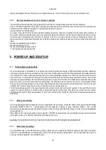
Regulation pressure
greater than SP
FL setting too high
Reduce minimum operating frequency FL (if electric pump enables this)
The display shows
SC
Short circuit between phases
Ensure that the motor is in the correct condition and check connections to the latter
The pump never stops
1) Minimum flow threshold FT setting too low.
2) Setting a minimum frequency of power off
FZ too low (*).
2) Short observation time(*).
3) Unstable pressure regulation(*).
4) Incompatible use (*).
1) Set a higher FT threshold
2) Set a higher FZ threshold
3) Wait for the self-learning process (*) or run quick learning mode (see para 6.5.9.1.1)
3) Correct GI and GP(*) (see 6.6.4 and 6.6.5)
4) Ensure that the system meets the operating requirements without the flow sensor (*) (see
section 6.5.9.1). Attempt to reset by pressing MODE SET + - to recalculate conditions without
the flow sensor.
The pump stops even
when not required
1)Short observation time(*).
2) Minimum frequency FL setting too high (*).
3) Excessively high setting of minimum
shutdown frequency FZ (*).
1) Wait for the self-learning process (*) or run quick learning mode (see para 6.5.9.1.1).
2) If possible set a lower FL value(*).
3) Enter a lower threshold for FZ.
The multi inverter
system does not start
One or more inverters have an incorrect RC
current setting.
Check the RC current setting on each inverter.
The display shows:
Press + to align this
config
One or more inverters have sensitive
parameters not aligned
Press + on the inverter that has the most recent and correct configuration of parameters.
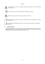
In a multiple inverter
system the parametres
are not propagatable
1) Different passwords
2) Presence of non-propagatable
configurations
1) access each inverter individually and enter the same password on all, or remove the
password. See para. 6.6.16
2) modify the configuration so that it is propagatable; it is not admitted to propagate
configurations with FI=0 or FZ=0. See paragraph 4.2.2.2
(*) The asterisk refers to cases of systems without the flow sensor
Table 16: Troubleshooting
Summary of Contents for MCE-150/P
Page 308: ...306 IEC 60634 1...
Page 309: ...307 1 6 1 1...
Page 312: ...310 1 2 1 1 1 1 2 5 2 1 2 1 2...
Page 313: ...311 2 1 1 2 1 2 L L L 2 2 4 2 15 2 2 1 1a...
Page 314: ...312 2a 3a 4b 1b 127 240 240 480...
Page 318: ...316 GP GI 6 6 4 6 6 5 7 A B C D...
Page 323: ...321 50 60 7 DC AC 50 60 8 6 2 1 5 36 36 12 3 3 3 3 2 13 9 10 8...
Page 325: ...323 I1 F1 I1 6 6 13 2 I2 P2 6 6 13 3 I3 F3 6 6 13 4 I4 1 F4 6 6 13 5 10 GND 7 I1 I2 I3 I4...
Page 326: ...324 3 13 64 X 128 4 MODE SET 11 SET 9 MODE 1 SET 11 3 EEprom SET 6 SET MODE 3 1 11...
Page 327: ...325 3 2 1 2 3 2 1 MODE SET MODE 10 2 2 5 5 5 2 2 12...
Page 329: ...327 12 SET 14 15 13 15 3 3...
Page 331: ...329 15 14 3 4 PW 6 6 16 GO SB...
Page 332: ...330 4 4 1 Link 8 4 2 4 2 1 Link Link 15...
Page 333: ...331 17 Link 4 2 2 0 5V 4 20 A 0 4 2 2 1 FI FI 4 2 2 2 FZ 6 5 9 1 4 2 2 3 0 5 4 20 A 0 5 0...
Page 336: ...334 4 4 2 2 4 2 5 4 5 ET 6 6 9 FL 4 5 1 4 5 1 1 ET ET ET ET 0 ET 6 6 9 4 5 1 2 23 23...
Page 339: ...337 FZ FZ 2 35 FZ 37 FZ FZ FZ FZ FI 0 FZ FZ 0 5 1 7 6 GI GP FL TB...
Page 362: ...360 OC 10 6 OF 10 6 33 8 8 1 PMW 4 2 8 2 8 3 8 3 SET EE EEprom FLASH...
Page 548: ...546 IEC 364 1 inverter...
Page 549: ...547 1 Inverter inverter inverter 6 inverter 1 1...
Page 552: ...550 1 2 1 1 inverter inverter 1 1 2 5 inverter inverter 2 1 inverter inverter 2 1 2 C...
Page 554: ...552 2a 3a 4b...
Page 558: ...556 GP GI 6 6 4 6 6 5 inverter 7 A B C D...
Page 567: ...565 3 2 1 2 3 2 1 MODE SET Setpoint MODE 10 ONOMA TOY MENOY 2 Setpoint 2 5 5 5 2 2 12...
Page 571: ...569 15 15 14 3 4 Password inverter password password inverter password PW 6 6 16 GO SB FAULT...
Page 728: ...726 IEC 364 1 1...
Page 729: ...727 1 1...
Page 732: ...730 1 2 1 1 1 2 5 2 1 2 1 2 C...
Page 733: ...731 2 1 1 0 2 1 2 L L L 2 2 4 2 15 2 2 1 1...
Page 734: ...732 2a 3a 4b...
Page 738: ...736 GP GI 6 6 4 6 6 5 7 2 2 3 2 Press Flow 6 A B C D...
Page 743: ...741 DC AC 50 60 Hz 7 DC V AC 50 60 Hz Vrms V 8 6 V 2 1 5 V 36 36 12V A 3 3 3 3 2 13 8 10 8...
Page 744: ...742 12 J5 I1 11 17 16 18 16 17 I2 11 15 16 18 15 16 I3 11 14 13 18 13 14 I4 11 12 13 8 12 13 9...
Page 746: ...744 3 13 Oled 64 X 128 4 MODE SET 11 SET or 9 MODE 1 SET 10 3 EEprom SET SET or MODE...
Page 751: ...749 14 14 3 4 PW 6 6 16 GO SB FAULT...
Page 752: ...750 4 4 1 Link 8 4 2 4 2 1 Link Link 15...
Page 966: ...964 IEC 60634 1...
Page 967: ...965 1 6 1 1...
Page 970: ...968 1 2 5 2 1 2 1 2 2 1 1...
Page 971: ...969 2 1 2 L L L 2 2 4 2 15 2 2 1 1a 1a...
Page 976: ...974 3 2 2 3 2 Press Flow 6 A B C D...
Page 981: ...979 50 60 7 DC AC 50 60 8 6 2 1 5 36 36 12 3 3 3 3 2 13 2 10 8...
Page 982: ...980 5 J5 I1 11 17 16 18 16 17 I2 11 15 16 18 15 16 I3 11 14 13 18 13 14 I4 11 12 13 8 12 13 8...
Page 984: ...982 SET 9 3 EEprom SET 6 SET MODE 3 1 11 3 2 1 2 3 2 1 MODE SET MODE 10 2 2 5 5...
Page 986: ...984 4 3 2 2 12 SET 7 15 13...
Page 987: ...985 8 3 3 psi 12 GO SB BL LP HP EC...
Page 989: ...987 PW 6 6 16 4 4 1 Link 8 4 2 4 2 1 Link Link 15...
Page 993: ...991 4 4 2 2 4 2 5 4 5 ET 6 6 9 FL 4 5 1 4 5 1 1 ET ET ET ET 0 ET 6 6 9 4 5 1 2 23 23...
Page 1020: ......
Page 1021: ......
Page 1022: ......
Page 1023: ......


