D-Link DXS-3410 Series Hardware Installation Manual Download Page 41


Subject to the terms and conditions set forth herein, D-Link Systems, Inc. (“D-Link”) provides this Limited Warranty: 


Only to the person or entity that originally purchased the product from D-Link or its authorized reseller or distributor, and 


Only for products purchased and delivered within the fifty states of the United States, the District of Columbia, U.S. Possessions or Protectorates, 

U.S. Military Installations, or addresses with an APO or FPO. 


Limited Warranty:


D-Link warrants that the hardware portion of the D-Link product described below (“Hardware”) will be free from material defects in 

workmanship and materials under normal use from the date of original retail purchase of the product, for the period set forth below (“Warranty Period”), 

except as otherwise stated herein.  


Limited Lifetime Warranty for the product is defined as follows: 


Hardware: For as long as the original customer/end user owns the product, or five (5) years after product discontinuance, whichever occurs first 

(excluding power supplies and fans) 


Power supplies and fans: Three (3) Year 


Spare parts and spare kits: Ninety (90) days 


The customer's sole and exclusive remedy and the entire liability of D-Link and its suppliers under this Limited Warranty will be, at D-Link’s option, to 

repair or replace the defective Hardware during the Warranty Period at no charge to the original owner or to refund the actual purchase price paid.  Any 

repair or replacement will be rendered by D-Link at an Authorized D-Link Service Office.  The replacement hardware need not be new or have an identical 

make, model or part.  D-Link may, at its option, replace the defective Hardware or any part thereof with any reconditioned product that D-Link reasonably 

determines is substantially equivalent (or superior) in all material respects to the defective Hardware.  Repaired or replacement hardware will be 

warranted for the remainder of the original Warranty Period or ninety (90) days, whichever is longer, and is subject to the same limitations and exclusions.  

If a material defect is incapable of correction, or if D-Link determines that it is not practical to repair or replace the defective Hardware, the actual price 

paid by the original purchaser for the defective Hardware will be refunded by D-Link upon return to D-Link of the defective Hardware.  All Hardware or part 

thereof that is replaced by D-Link, or for which the purchase price is refunded, shall become the property of D-Link upon replacement or refund. 


Limited Software Warranty:  

D-Link warrants that the software portion of the product (“Software”) will substantially conform to D-Link’s then current 

functional specifications for the Software, as set forth in the applicable documentation, from the date of original retail purchase of the Software for a period 

of ninety (90) days (“Software Warranty Period”), provided that the Software is properly installed on approved hardware and operated as contemplated in 

its documentation. D-Link further warrants that, during the Software Warranty Period, the magnetic media on which D-Link delivers the Software will be 

free of physical defects.  The customer's sole and exclusive remedy and the entire liability of D-Link and its suppliers under this Limited Warranty will be, 

at D-Link’s option, to replace the non-conforming Software (or defective media) with software that substantially conforms to D-Link’s functional 

specifications for the Software or to refund the portion of the actual purchase price paid that is attributable to the Software.  Except as otherwise agreed 

by D-Link in writing, the replacement Software is provided only to the original licensee, and is subject to the terms and conditions of the license granted by 

D-Link for the Software.  Replacement Software will be warranted for the remainder of the original Warranty Period and is subject to the same limitations 

and exclusions.  If a material non-conformance is incapable of correction, or if D-Link determines in its sole discretion that it is not practical to replace the 

non-conforming Software, the price paid by the original licensee for the non-conforming Software will be refunded by D-Link; provided that the non-

conforming Software (and all copies thereof) is first returned to D-Link.  The license granted respecting any Software for which a refund is given 

automatically terminates. 


Non-Applicability of Warranty:  

The Limited Warranty provided hereunder for Hardware and Software portions of D-Link's products will not be applied to 

and does not cover any refurbished product and any product purchased through the inventory clearance or liquidation sale or other sales in which D-Link, 

the sellers, or the liquidators expressly disclaim their warranty obligation pertaining to the product and in that case, the product is being sold "As-Is" 

without any warranty whatsoever including, without limitation, the Limited Warranty as described herein, notwithstanding anything stated herein to  the 

contrary.


Submitting A Claim

:  The customer shall return the product to the original purchase point based on its return policy.  In case the return policy period has 

expired and the product is within warranty, the customer shall submit a claim to D-Link as outlined below: 


The customer must submit with the product as part of the claim a written description of the Hardware defect or Software nonconformance in sufficient 

detail to allow D-Link to confirm the same, along with proof of purchase of the product (such as a copy of the dated purchase invoice for the product) 

if the product is not registered. 


The customer must obtain a Case ID Number from D-Link Technical Support at 1-877-453-5465, who will attempt to assist the customer in resolving 

any suspected defects with the product.  If the product is considered defective, the customer must obtain a Return Material Authorization (“RMA”) 

number by completing the RMA form and entering the assigned Case ID Number at 

https://rma.dlink.com/


After an RMA number is issued, the defective product must be packaged securely in the original or other suitable shipping package to ensure that it 

will not be damaged in transit, and the RMA number must be prominently marked on the outside of the package.  Do not include any manuals or 

accessories in the shipping package.  D-Link will only replace the defective portion of the product and will not ship back any accessories. 


The customer is responsible for all in-bound shipping charges to D-Link.  No Cash on Delivery (“COD”) is allowed.  Products sent COD will either be 

rejected by D-Link or become the property of D-Link.  Products shall be fully insured by the customer and shipped to 

D-Link Systems, Inc., 17595 

Mt. Herrmann, Fountain Valley, CA 92708

.  D-Link will not be held responsible for any packages that are lost in transit to D-Link.  The repaired or 

replaced packages will be shipped to the customer via UPS Ground or any common carrier selected by D-Link.  Return shipping charges shall be 

prepaid by D-Link if you use an address in the United States, otherwise we will ship the product to you freight collect. Expedited shipping is available 

upon request and provided shipping charges are prepaid by the customer. 


D-Link may reject or return any product that is not packaged and shipped in strict compliance with the foregoing requirements, or for which an RMA 

number is not visible from the outside of the package. The product owner agrees to pay D-Link’s reasonable handling and return shipping charges for any 

product that is not packaged and shipped in accordance with the foregoing requirements, or that is determined by D-Link not to be defective or non-

conforming. 


What Is Not Covered: 

The Limited Warranty provided herein by D-Link does not cover: Products that, in D-Link’s judgment, have been subjected to 

abuse, accident, alteration, modification, tampering, negligence, misuse, faulty installation, lack of reasonable care, repair or service in any way that is not 

contemplated in the documentation for the product, or if the model or serial number has been altered, tampered with, defaced or removed; Initial 

installation, installation and removal of the product for repair, and shipping costs; Operational adjustments covered in the operating manual for the product, 

and normal maintenance; Damage that occurs in shipment, due to act of God, failures due to power surge, and cosmetic damage;  Any hardware, 

software, firmware or other products or services provided  by anyone other than D-Link; and Products that have been purchased from inventory clearance 

or liquidation sales or other sales in which D-Link, the sellers, or the liquidators expressly disclaim their warranty obligation pertaining to the product.  

While necessary maintenance or repairs on your Product can be performed by any company, we recommend that you use only an Authorized D-Link 

Service Office. Improper or incorrectly performed maintenance or repair voids this Limited Warranty. 


Disclaimer of Other Warranties: 

EXCEPT FOR THE LIMITED WARRANTY SPECIFIED HEREIN, THE PRODUCT IS PROVIDED “AS-IS” WITHOUT 

ANY WARRANTY OF ANY KIND WHATSOEVER INCLUDING, WITHOUT LIMITATION, ANY WARRANTY OF MERCHANTABILITY, FITNESS FOR A 

PARTICULAR PURPOSE AND NON-INFRINGEMENT. IF ANY IMPLIED WARRANTY CANNOT BE DISCLAIMED IN ANY TERRITORY WHERE A 

PRODUCT IS SOLD, THE DURATION OF SUCH IMPLIED WARRANTY SHALL BE LIMITED TO NINETY (90) DAYS. EXCEPT AS EXPRESSLY 

COVERED UNDER THE LIMITED WARRANTY PROVIDED HEREIN, THE ENTIRE RISK AS TO THE QUALITY, SELECTION AND PERFORMANCE 

OF THE PRODUCT IS WITH THE PURCHASER OF THE PRODUCT. 


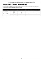
Summary of Contents for DXS-3410 Series

Page 1: ...Version 1 00 2023 12 18...

Page 2: ...wo conditions 1 This device may not cause harmful interference and 2 this device must accept any interference received including interference that may cause undesired operation CE Mark Warning This eq...

Page 3: ...nstalling the AC Power Cord Retainer 10 Installing the Redundant Power Supply RPS 12 Connecting the DPS 500A RPS to the Switch 12 4 Switch Connections 14 Stacking the Switch 14 Switch to Switch 17 Swi...

Page 4: ...Layer 3 Stackable Managed Switch Hardware Installation Guide iv Pr cautions de s curit 32 General Precautions for Rack Mountable Products 34 Protecting Against Electrostatic Discharge 35 Warranty Tech...

Page 5: ...e Switch throughout this manual Typographical Conventions Convention Description Boldface Font This convention is used to emphasize keywords It also denotes a button toolbar icon menu or menu items Fo...

Page 6: ...r inactive links and by allowing ports to autonomously enter a hibernated state This intelligent approach ensures efficiency and sustainability Switch Series The following switches are part of the DXS...

Page 7: ...s additional storage space for firmware images and configuration files that can be copied to and from the Switch Only endpoint devices like USB flash drives are supported Console Port The console port...

Page 8: ...at the same time on the SFP28 ports in this switch series Front Panel LED Indicators The LED indicators provide valuable information in a variety of ways like their color blinking times and location F...

Page 9: ...ived through the port Amber On Solid Active 100 1000 Mbps connection through the port On Blinking Data transmitted and received through the port Off Inactive connection no link present or port disable...

Page 10: ...and cable set should be acquired separately Redundant Power Supply The RPS port can be utilized to connect an optional external load sharing RPS to the Switch In the event of internal power failure t...

Page 11: ...ambient temperature the speed of the fan s will change Fan Mode Fan Status DXS 3410 32XY DXS 3410 32SY Normal mode Ultra Low Below 12 C Below 17 C Very Low Above 15 C Ultra Low to Very Low Below 27 C...

Page 12: ...s section provides guidance for users installing the Switch in a location outside of a Switch rack Affix the provided rubber feet to the underside of the Switch Please be aware that there are designat...

Page 13: ...19 1U rack using the rack mounting kit included in the package contents Fasten the mounting brackets to the sides of the Switch using the screws provided Figure 3 2 Attaching the rack mounting bracke...

Page 14: ...considerable distances While RJ45 wiring connections have a maximum reach of 100 meters fiber optic connections can extend over several kilometers The figure below illustrates the procedure for inser...

Page 15: ...of a power failure as a precautionary measure disconnect the power cord from the Switch After power is restored reconnect the power cord to the Switch s power socket Installing the AC Power Cord Reta...

Page 16: ...tie wrap until the end of the cord Circle the tie of the retainer around the power cord and into the locker of the retainer Figure 3 7 Slide the Retainer through the Tie Wrap Figure 3 8 Circle around...

Page 17: ...Ethernet Switches and it can be linked to the RPS port of the Switch using a 14 pin DC power cable A standard three pronged AC power cable is used to connect the RPS to the main power source CAUTION...

Page 18: ...onfirm the presence and operation of the RPS No software configuration is necessary CAUTION Leave at least 15 cm 6 inches of space at the rear of the Switch when an RPS is installed to prevent cable d...

Page 19: ...nistrators aiming to upgrade their networks leveraging the stacking ports for scaling and stacking purposes This ultimately enhances overall reliability serviceability and availability The Switch supp...

Page 20: ...DXS 3410 Series Layer 3 Stackable Managed Switch Hardware Installation Guide 15 In the following diagram Switches are stacked in the Duplex Chain topology Figure 4 1 Duplex Chain Stacking Topology...

Page 21: ...DXS 3410 Series Layer 3 Stackable Managed Switch Hardware Installation Guide 16 In the following diagram Switches are stacked in the Duplex Ring topology Figure 4 2 Duplex Ring Stacking Topology...

Page 22: ...6 UTP STP cables For 10GBASE T connections to the Switch use Category 6a 7 UTP STP cables For fiber optic connections to the Switch s SFP SFP28 ports make use of the appropriate fiber optic cables Fi...

Page 23: ...DXS 3410 Series Layer 3 Stackable Managed Switch Hardware Installation Guide 18 The diagram below displays a Server connected to the Switch Figure 4 5 Switch to End Node Server...

Page 24: ...offer an in band connection to the CLI using Telnet or SSH NOTE For more information about the CLI refer to the DXS 3410 Series CLI Reference Guide Connecting to the Console Port The Console port is u...

Page 25: ...assword Switch Configuring the IP Address To be able to access the Web UI or the CLI via Telnet SSH we need to know what the IP address of the Switch is The default IP address is 10 90 90 90 with a su...

Page 26: ...nnection to the Web UI using HTTP or HTTPS SSL The Web UI examples in this guide was capture using the Microsoft Edge browser Connecting to the Web UI By default Secure HTTP https access is available...

Page 27: ...witch Hardware Installation Guide 22 The following is a screen capture of the Web User Interface Web UI Figure 5 3 Web User Interface Standard Mode NOTE For more information about the Web UI refer to...

Page 28: ...nagers can view read only information or receive traps using SNMP version 1 while another group can be endowed with higher security levels entailing read write privileges via SNMP version 3 With SNMP...

Page 29: ...r Consumption Maximum DXS 3410 32XY 100 VAC 60 Hz 108 5 Watts 240 VAC 50 Hz 109 0 Watts DXS 3410 32SY 100 VAC 60 Hz 103 5 Watts 240 VAC 50 Hz 104 0 Watts Power Consumption Standby DXS 3410 32XY 100 VA...

Page 30: ...ity Queues Supports the following Maximum of 8 Priority Queues per port Link Aggregation Supports the following Maximum of 32 groups per device Maximum of 8 ports per group Static Routes Supports the...

Page 31: ...auto speed functions are not supported IEEE 802 3x flow control for the full duplex mode All SFP ports are backwards compatible to support SFP transceivers 25G SFP28 Ports Standards IEEE 802 3ae 10GBA...

Page 32: ...m WDM BiDi SFP DEM 436XT BXD 10GBASE LR Single mode 20 km 1330 nm 1270 nm WDM BiDi SFP DEM 436XT BXU 10GBASE LR Single mode 20 km 1270 nm 1310 nm SFP28 DEM S2801SR 25GBASE SR Multi mode 100 m 850 nm S...

Page 33: ...diagrams and tables show the standard RJ45 receptacle connector and their pin assignments Figure B 1 Standard RJ45 port and connector RJ45 Pin Assignment Contact MDI X Port MDI II Port 1 RD receive TD...

Page 34: ...h to access the command line interface The following diagram and table show the standard RJ45 to RS 232cable and pin assignments Figure B 2 Console to RJ45 Cable RJ45 To RS 232 Cable Pin Assignment Ta...

Page 35: ...rmation Only hardware based ERPS supports the Fast Link Drop Interrupt feature with a recovery time of 50 milliseconds in a 16 node ring The distance must be less than 1200 kilometers Model Name ERPS...

Page 36: ...ny objects into the openings of the system Doing so can cause fire or electric shock by shorting out interior components Only use this product with approved equipment Allow the product to cool before...

Page 37: ...pe the Middle East Africa and the Far East CAUTION Risk of Explosion if Battery is replaced by an Incorrect Type Dispose of Used Batteries According to the Instructions ATTENTION Risque d explosion si...

Page 38: ...bles sont quip s de fiches trois broches pour garantir une mise la masse appropri e N utilisez pas d adaptateur de prise et n liminez pas la broche de mise la masse du c ble Si un c ble de rallonge e...

Page 39: ...item in the rack first Make sure that the rack is level and stable before extending a component from the rack Use caution when pressing the component rail release latches and sliding a component into...

Page 40: ...sis The following steps can also be taken prevent damage from electrostatic discharge ESD When unpacking a static sensitive component from its shipping carton do not remove the component from the anti...

Page 41: ...quidators expressly disclaim their warranty obligation pertaining to the product and in that case the product is being sold As Is without any warranty whatsoever including without limitation the Limit...

Page 42: ...pyright Statement No part of this publication or documentation accompanying this product may be reproduced in any form or by any means or used to make any derivative such as translation transformation...

Page 43: ...egistration Register your D Link product online at http support dlink com register Product registration is entirely voluntary and failure to complete or return this form will not diminish your warrant...

Page 44: ...nfiguration Please refer to the user manual to learn more or visit http www mydlink com for more information Also feel free to contact us U S and Canadian customers can contact D Link Technical Suppor...

Page 45: ...ASSISTANCE TECHNIQUE ASISTENCIA T CNICA SUPPORTO TECNICO TECHNISCHE ONDERSTEUNING POMOC TECHNICZNA TECHNICK PODPORA TECHNIKAI T MOGAT S TEKNISK ST TTE TEKNISK SUPPORT TEKNINEN TUKI TEKNISK SUPPORT ASS...

Page 46: ...donesia www dlink co id Malaysia www dlink com my Philippines www dlink com ph Vietnam www dlink com vn Korea customers Tel 1899 3540 Monday to Friday 9 30am to 6 30pm Web http d link co kr E mail sup...

Page 47: ...enter no 202 25866777 General Inquiries info eg me dlink com Kingdom of Saudi Arabia Riyadh Saudi Arabia E Mail info sa me dlink com Pakistan Karachi Office D 147 1 KDA Scheme 1 Opposite Mudassir Park...

Page 48: ...D Link D Link D Link D Link D Link 8 800 700 5465 http www dlink ru e mail support dlink ru 114 3 289 390043 16 7 4912 503 505...

Page 49: ...375 17 218 13 65 E mail support dlink by c 143 7 727 378 55 90 E mail almaty dlink ru 3 23 5 374 10 39 86 67 info dlink am Lietuva Vilnius irm n 139 303 Tel 370 5 236 36 29 E mail info dlink lt Eesti...

Page 50: ...inkla com soporte call center Soporte T cnico de D Link a trav s de Internet Horario de atenci n Soporte T cnico en www dlinkla com e mail soporte dlinkla com consultas dlinkla com Clientes de Brasil...

Page 51: ...nk D Link D Link 0800 002 615 02 6600 0123 8715 http www dlink com tw dssqa_service dlink com tw http www dlink com tw D Link http www dlink com hk http www dlink com hk contact html D Link www dlink...

Page 52: ...us web D Link Dukungan Teknis untuk pelanggan Tel 0800 14014 97 Layanan Bebas Pulsa Dukungan Teknis D Link melalui Internet Pertanyaan Umum sales id dlink com Bantuan Teknis support id dlink com Websi...

Page 53: ...site 1 employee 2 9 10 49 50 99 100 499 500 999 1000 or more 3 What network protocol s does your organization use XNS IPX TCP IP DECnet Others_____________________________ 4 What network operating sys...

Page 54: ......

Reviews: