User Manual
Version 2.00 | June 20, 2017
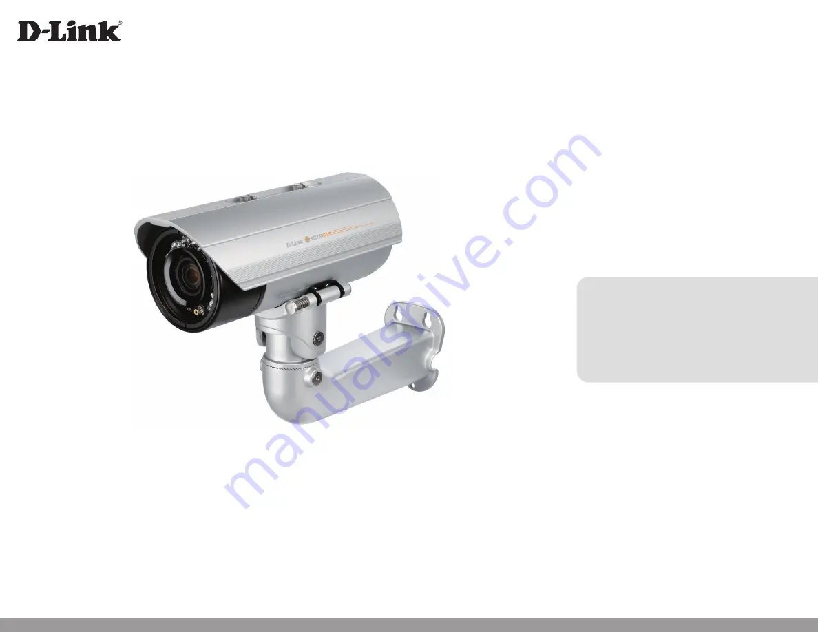
DCS-7517
5 Megapixel H.265 Outdoor Network Camera
Page 1: ...User Manual Version 2 00 June 20 2017 DCS 7517 5 Megapixel H 265 Outdoor Network Camera ...
Page 2: ...on 2 00 June 26 2017 DCS 7517 Revision B1 with firmware version 2 00 Trademarks D Link and the D Link logo are trademarks or registered trademarks of D Link Systems or its subsidiaries in the United States or other countries All other company or product names mentioned herein are trademarks or registered trademarks of their respective companies Copyright 2017 D Link Systems All rights reserved Thi...
Page 3: ...k Connection 21 Connecting Using Power over Ethernet 21 Connecting with a 12 V DC Power Adapter not included 22 Software Installation 23 Configuration 26 Using the Configuration Interface 26 Live Video 27 Setup Wizard 29 Network Setup Wizard 30 Motion Detection Setup Wizard 32 Settings 35 Network Settings 35 LAN Settings 35 IPv6 36 PPPoE 36 HTTP and HTTPS 37 RTSP and Multicast 39 Bonjour 40 Camera...
Page 4: ...on 71 Factory Reset 72 Reboot Device 73 Firmware Update 74 DI and DO 75 Camera Options 76 Device Info 76 System Time 77 Time Settings 77 Auto Time Config 78 Set Date and Time 79 Administration Settings 80 Admin Password 80 User Accounts 81 User List 82 Camera Log 83 DI DO Specifications 84 Technical Specifications 85 Regulatory Information 88 ...
Page 5: ...ackage Contents If any of the above items are missing please contact your reseller DCS 7517 5 Megapixel H 265 Outdoor Network Camera CAT5 Ethernet Cable CD ROM with User Manual and Software Quick Installation Guide Mounting Plate Mounting Bracket and Hardware Alignment Sticker ...
Page 6: ...nd outdoor applications The built in removable IR cut filter and IR LEDs give the DCS 7517 the capability to view up to 30 meters at night The DCS 7517 also incorporates Power over Ethernet PoE allowing it to be easily installed in a variety of locations without the need for supplemental power cabling The combination of IP66 housing IR cut filter IR LEDs and PoE make the DCS 7517 an ideal solution...
Page 7: ... balances fan use for a built in heater based on a range of preset thermostatic settings This gives the DCS 7517 the ability to perform in the most demanding environments Remote Monitoring Utility The D ViewCam application adds enhanced features and functionality for the DCS 7517 and allows administrators to configure and access the camera from a remote site via the Internet Other features include...
Page 8: ... shield 4 Camera Lens Varifocal lens to record video of the surrounding area 5 Power Status LED Indicates the camera s current status 6 Light Sensor Measures lighting conditions and switches between day and night mode accordingly 7 Quick Release Pin Allows the camera to be swiveled into position for easy maintenance 8 Camera Shoe Adjustable mounting seat for the camera 9 Ethernet Jack Connects to ...
Page 9: ...O connectors for external devices 12 V DC output not supported for the DCS 7517 12 Reset Button Press and hold the button for 10 seconds to reset the camera back to the factory default settings 13 24 V Power Connector Not supported for the DCS 7517 14 Power Connector Power connector for a 12 V DC power adapter not included 15 Audio Out Green Connects to a speaker 16 Audio In Red Connects to a micr...
Page 10: ...sert an SD card for local storage for storing recorded images and video 19 Ethernet Port Connects to Ethernet cable 20 Harness Connector Connects to the optional cable harness not included 1 12V IN 2 GND 3 AUD IN 4 AUD GND 5 AUD OUT 6 12V OUT 7 GND 8 RESET 9 DI 10 DO 21 Reset Button Press and hold the button for 10 seconds to reset the camera back to the factory default settings 18 20 21 19 1 10 ...
Page 11: ...7517 User Manual Section 2 Installation Installation Connecting the Optional Cable Harness Step 1 Remove the back camera cover by turning it counter clockwise Step 2 Remove the back waterproofing plug from the camera ...
Page 12: ...ction 2 Installation Step 3 Push the camera connector and cable through the hole and insert the cable s waterproofing plug Make sure the plug is inserted properly to ensure a good seal Step 4 Connect the camera connector to the camera ...
Page 13: ...13 D Link DCS 7517 User Manual Section 2 Installation Step 5 Reattach the back camera cover by turning it clockwise Note Make sure that the weatherproof seals are secured firmly in place ...
Page 14: ... Step 1 Remove the back camera cover by turning it counter clockwise Step 2 Insert your microSD card into the slot with the contacts facing down Step 3 Reattach the back camera cover by turning it clockwise Note Make sure that the weatherproof seals are secured firmly in place ...
Page 15: ...nd put them side by side Step 2 Pass the individual cables into the mounting bracket ensuring the head of each has fully passed through the bend Step 3 Once all the cables are in the mounting bracket push the cable until you are able to pull them through the base of the bracket Step 4 Attach the camera bracket to the mounting bracket following the steps outlined in Attaching the Camera to the Moun...
Page 16: ...attaching the camera to the mounting bracket ensure the camera shoe is oriented correctly for its final position For instructions on how to orient the camera shoe skip to Orienting the Camera on page 18 Step 1 Using the two screws provided attach the quick release retention clip to the bottom of the camera ...
Page 17: ...he quick release pin to reveal the attachment notches Step 3 Align the quick release retention clip over the quick release pin Step 4 Allow the quick release pin to return to its original position Step 5 Using the provided hex key tighten the two remaining bolts 3 2 5 ...
Page 18: ...ts on both sides of the camera shoe This will allow you to adjust the vertical orientation of the camera Firmly tighten the adjustment bolts on both sides of the camera shoe after making your adjustments Step 2 Loosen the adjustment bolts on both sides of the mounting bracket This will allow you to adjust the horizontal orientation of the camera Firmly tighten the adjustment bolts on both sides of...
Page 19: ...ical Specifications on page 85 for additional reference Step 2 Use a 6 mm drill bit to make the holes approximately 30 mm deep Step 3 Remove the alignment sticker Deploying the Camera Before deploying the camera to a fixed location it is recommended that you take a photo from the desired location to ensure an adequate field of view Step 4 Insert the wall anchors and affix the mounting plate using ...
Page 20: ...uspend the camera and mounting bracket from the two lugs on the mounting plate Step 6 Fasten the camera firmly to the mounting plate using the screw provided ensuring clear passage for the cables through the cable channel or via the mounting plate cut out 5 5 6 6 ...
Page 21: ...ual Section 2 Installation If you are using a PoE switch connect the IP camera to a PoE switch with an Ethernet cable which will provide transmission of both power and data Connecting Using Power over Ethernet Network Connection ...
Page 22: ...ness not included you can power the camera using a 12 V DC power adapter not included Step 1 Connect the camera to a switch or router via an Ethernet cable Step 2 Connect a 12 V power adapter not included from the camera to a power outlet Connecting with a 12 V DC Power Adapter not included 2 1 ...
Page 23: ...ne by the MAC ID printed on the label on the back of each camera Step 1 Insert the D Link CD into your computer s drive to start the autorun program TheCD ROMwillopentheSetupWizard TheSetupWizardwillguideyouthroughtheinstallation process to configure your camera Note If the autorun program does not automatically start on your computer go toWindows click the Start button and then type D autorun exe...
Page 24: ...n for the first time the default Admin ID is admin with the password left blank Click Next to continue Step 5 Select DHCP if your camera automatically obtains an IP address from a DHCP server such as a router Select Static IP if you want to manually enter the IP settings for the camera Click Next to continue ...
Page 25: ...nfirm your settings and click Restart TheLEDonthefrontofthecamerawillblink thenturnsolidgreenonceitsuccessfullyconnects to your network Step 7 Your camera is now set up Click Exit to exit the wizard and can skip to Configuration on page 26 for advanced configuration of your camera ...
Page 26: ...e IP address of your camera into a web browser To log in use the User name admin and the password you created in the Installation Wizard If you did not create a password the default password is blank After entering your password click OK Step 1 Select the camera and click the Link button to access the web configuration The Setup Wizard will automatically open your web browser to the IP address of ...
Page 27: ...from the toolbar This lets you create a custom toolbar with only the options you want Window Size You can choose between various screen sizes for your camera s video Auto Screen Automatically resize the camera video to match your browser window Full Screen View your camera video using the entire screen 100 Screen View your camera s video at 100 size 50 Screen View your camera s video at 50 size 25...
Page 28: ... Select a storage folder to save snapshots and video clips to Global View This will show a thumbnail of your camera s full view This can be useful when you are zooming in on the video in the Live Video screen Zoom In Out Click this and use the slider to zoom in and out of your camera s video You can find these icons in the top right corner of the Live Video screen Alarm This will flash red when mo...
Page 29: ...p your camera s network and motion detection settings Network Setup Wizard Motion Detection Setup Wizard Click on this button to start the Network Setup Wizard Refer to Network Setup Wizard on page 30 Click on this button to start the Motion Detection Setup Wizard Refer to Motion Detection Setup Wizard on page 32 ...
Page 30: ... Internet If your camera is connected to a router or you are unsure how your camera will connect to the Internet select DHCP Select Static IP Client if your Internet Service Provider has provided you with connection settings or if you wish to set a static address within your home network Enter the correct configuration information and click Next to continue If you are using PPPoE select PPPoE and ...
Page 31: ... Enable DDNS and enter your host information Click Next to continue Enter a name for your camera and click Next to continue Configure the correct time to ensure that all events will be triggered as scheduled Click Next to continue Confirm the settings are correct and click Apply to save them The settings will be saved to the DCS 7517 and the camera will restart ...
Page 32: ...ecify the detection sensitivity and define what parts of the camera s view to monitor for motion You may specify whether the camera should capture a snapshot record a video clip or save a system log when motion is detected Please refer to Motion on page 61 for more information about how to configure motion detection Step 2 This step allows you to enable motion detection based on a customized sched...
Page 33: ...tion 3 Configuration Step 3 This step allows you to specify where to send the snapshot video clip system log when motion is detected Select E mail FTP Network Storage or SD Card and enter the relevant information Click Next to continue ...
Page 34: ...ser Manual Section 3 Configuration Step 4 You have completed the Motion Detection Wizard Please verify your settings and click Finish to save them Please wait a few moments while the camera saves your settings and restarts ...
Page 35: ... an IP address automatically If you choose DHCP you do not need to fill out the IP address settings You may obtain a static or fixed IP address and other network information from your network administrator for your camera A static IP address may simplify access to your camera in the future Enter the fixed IP address in this field This number is used to determine if the destination is in the same s...
Page 36: ... host gateway and DNS server IPv6 Use this section to configure your camera s IPv6 settings After making any changes click the Save button to save your changes PPPoE Enable PPPoE User Name Password PPPoE Status Enable this setting if your network uses PPPoE Enter the username and password for your PPPoE account Re enter your password in the Confirm Password field You may obtain this information fr...
Page 37: ...rt Access Name for Stream 1 3 The default port number is 80 The default name is video mjpg where is the number of the stream HTTP Use this section to configure the HTTP and HTTPS access settings for your camera After making any changes click the Save button to save your changes ...
Page 38: ...rt number is 443 Enable the HTTPS service Choose the way the certificate should be created Three options are available Create a self signed certificate automatically Create a self signed certificate manually Create a certificate request and install Displays the status of the certificate The certificate cannot be removed while the HTTPS is still enabled To remove the certificate you must first unch...
Page 39: ... address of a particular stream For instance live1 sdp can be accessed at rtsp x x x x video1 sdp where the x x x x represents the ip address of your camera Use this section to configure your camera s RTSP and multicast stream settings After making any changes click the Save button to save your changes RTSP Multicast Multicast for Stream 1 2 3 The DCS 7517 allows you to multicast each of the avail...
Page 40: ...is section to enable Bonjour which allows your camera to be accessed more easily on your network After making any changes click the Save button to save your changes Bonjour Bonjour Name Enable this to enable Bonjour support Enter a name to identify this camera on Bonjour ...
Page 41: ...ll be added to the file name prefix when creating a snapshot or a video clip You may specify whether or not to illuminate the status LED on the camera Camera Settings Device Settings Use this section to configure the device name and LED behavior for your camera After making any changes click the Save button to save your changes ...
Page 42: ...om Auto Outdoor Indoor Fluorescent and Push Hold If you choose Push Hold hold a white card or grey card in front of the camera then click the Save button to set the camera s white balance Changes the exposure mode Use the drop down box to set the camera for Indoor Outdoor or Night environments or to Moving to capture moving objects The Low Noise option will focus on creating a high quality picture...
Page 43: ... this setting to compensate for backlit subjects Adjust this setting to alter the color intensity strength This setting controls the amount of coloration from grayscale to fully saturated Specify a value from 0 to 128 to specify how much sharpening to apply to the image Wide Dynamic Range WDR helps improve exposure making it easier to see objects in very bright or dark areas of the camera s image ...
Page 44: ...s does not control when night mode will be used this only controls when these image settings will be used To control when night mode will be used refer to IR ICR on page 45 You can select between 1080P WDR which will give you a picture with better exposure and 1080P 60FPS which will give you smoother video with a higher frame rate This setting controls the amount of gain applied to incoming audio ...
Page 45: ...e text totherightofthedrop downboxshowswhatthecurrentlightingconditions are like and you can refresh this information by clicking the Refresh button Day mode enables the IR Cut Filter and turns off the IR LEDs Night mode disables the IR Cut Filter and turns on the IR LEDs Set Day Night mode using a schedule The camera will enter Day mode at the starting time and return to Night mode at the ending ...
Page 46: ...t this option to enable the time stamp display on the video screen Lens Control Focus Mode Zoom Focus Setting this to Automatic will allow the camera to automatically adjust its focus Setting this to Manual will bring up the Focus slider which you can use to manually adjust the camera focus Click anywhere on the bar to adjust the camera zoom If the Focus Mode is set to Manual this bar will appear ...
Page 47: ...w a portion of the full camera view and allows you to use ePTZ to move the camera view around and use preset points You can set the maximum frame rate to be 1 fps to 30 fps A higher frame rate provides smoother motion for videos and requires more bandwidth Lower frame rates will result in stuttering motion and require less bandwidth This adjusts how the camera manages the quality and bandwidth usa...
Page 48: ...Control is set to CBR you can set the bit rate to use for this video profile If the Rate Control is set to CVBR you can set the maximum bit rate this video profile can use Select the image quality level for the camera to try to maintain High quality levels will result in increased bit rates and use more bandwidth ...
Page 49: ... then click the Add button If an existing preset has been selected from the Preset List you can change its name by typing in a new name then clicking the Rename button Clickthisdrop downboxtoseealistofallthepresetsthathavebeencreated You can select one then click the GoTo button to change the displayed camera view to the preset Clicking the Remove button will delete the currently selected preset T...
Page 50: ...specify the following Server This is a destination for media to be sent to such as an e mail address or FTP server Media This is the media that will be sent such as snapshots video clips or a system log You can then set up Events and Recordings Event This is the actual trigger event that the camera is monitoring for and the action that it will take Event triggers include motion detection loss of n...
Page 51: ...nt Settings Record 1 To add a new server media event or recording item click Add A screen will appear and allow you to update the fields accordingly 2 To delete the selected item from the server media event or recording drop down menus click the Delete button next to it 3 Click on the name if an item to edit it Event MGMT ...
Page 52: ...il account If you want to use an FTP server for your server select this and enter the settings for your target FTP server If you want to use a network storage device for your server select this and enter its settings here If you want to use an inserted microSD card for your server select this Server You can configure a server for each server type and up to 5 FTP servers After making any changes cl...
Page 53: ... taken before the main event snapshot is taken Set the number of post event images to take Post event images are images taken after the main event snapshot is taken You can set up to 7 post event images to be taken For example If both the Send pre event images and Send post event images are set to four a total of 9 images are generated after a trigger is activated 1 pic 2 pic 3 pic 4 pic 5 pic 6 p...
Page 54: ... this option to set the media type to video clips Set the video profile to use as the media source Refer to Video Stream on page 47 for more information on video profiles This sets how many seconds to record before the main event video clip starts You can record up to 4 seconds of pre event video Set the maximum length of video to record for your video clips Set the maximum file size to record for...
Page 55: ...tion events and digital input triggers Specify the input type that triggers the event Selecting this will trigger the event when motion is detected during live video monitoring Make sure you have enabled motion detection and specified what part of the image to monitor for motion For more details refer to Motion on page 61 Selecting this will trigger the event in specified intervals The trigger int...
Page 56: ...t to monitor for this event Select which days to monitor for this event then select Always or enter the time interval to monitor for the specified event Select the actions you want the camera to do when the event happens Select the Server to use then choose the Media you want to save to it Please note that you need to set up your Server and Media entries first You can also send a signal on the dig...
Page 57: ...e you want to record using the dropdown boxes Select where the recording file will be stored You should set up a Server entry for a network storage drive first Please input a HDD volume between 1 MB and 2TB for recording space The recording data will replace the oldest record when the total recording size exceeds this value For example if each recording file is 6 MB and the total cyclical recordin...
Page 58: ...al Section 3 Configuration Time of Each File for Recording File Name Prefix If this is selected files will be separated based on the maximum length you specify The prefix name will be added to the file name of the recording file s ...
Page 59: ...eting Files and Folders It means free space in storage Camera will not use this space to save any video or snapshot files Oldest files will be deleted when the system need to more storage space Use the drop down menu to specify how many files to show per page To change pages use the drop down menu on the right Click this to refresh the file and folder information from the microSD card Click this b...
Page 60: ...ndow clicktheAddbutton Aprivacymaskwindow will appear in the top left corner of the live video After moving and resizing the window how you wish click Save to save your changes To modify an existing privacy mask window click on the button next to the window s number then move and resize it as you wish You can delete the window by clicking the Delete button Defining Privacy Mask Windows Privacy Mas...
Page 61: ...ercentages can be useful when you are only monitoring a specific part of the camera s view such as a doorway Sethowsensitivemotiondetectionwillbefrom0 to100 Alowsensitivity means that there must be large changes between two images in order to detect motion and a high sensitivity means that even small changes will cause motion to be detected Low sensitivities may be useful when monitoring an area t...
Page 62: ...ndetection window will appear in the top left corner of the live video After moving and resizing the window how you wish click Save to save your changes To modify an existing motion detection window click on the button next to the window s number then move and resize it as you wish You can delete the window by clicking the Delete button Defining Motion Detection Windows ...
Page 63: ...uration in seconds The tamper alarm will be triggered only when there is a substantial change in the camera s view for longer than the trigger duration specified With tamper detection the camera is capable of detecting incidents such as redirection blocking or de focusing or even spray paint After making any changes click the Save button to save your changes ...
Page 64: ...abling this setting allows the camera to add port forwarding entries into the router automatically on a UPnP capable network If UPnP Port Forwarding is enabled you can set which port to use for forwarding If UPnP Port Forwarding is enabled this will show the UPnP Port Forwarding status Enabling Video Motion will allow your camera to use UPnP to automatically set up port forwarding on your router A...
Page 65: ...DDNS Server Address Host Name User Name Password Timeout Status Check this box to enable the DDNS function Enter your DDNS server address or select a service from the drop down menu Enter the host name of the DDNS server Enter the username or e mail address used to connect to the DDNS server Enter the password used to connect to the DDNS server You can set up how often the camera notifies the DDNS...
Page 66: ...me Enable this option to allow for SNMPv1 and SNMPv2c management of the camera Enter a name for the read write community of your SNMP server Enter a name for the read only community of your SNMP server Enable this option to allow SNMPv3 management of the camera Enter a name for the read write community of your read write SNMP server Enter the type of authentication used by your read write SNMP ser...
Page 67: ... password used for your read only SNMP server Enable SNMP traps support of the camera Enter IP address of SNMP server where the trap message will be sent Enter a name for trap community Enter IP address of SNMP server where the trap message will be sent Enter a name for trap community Authentication Type Authentication Password Encryption Password Traps Trap address Trap community Trap address 2 T...
Page 68: ...ype Identity Password CA Certificate Status Enable this to use IEEE 802 1x authentication Select the EAP type used by your 802 1x server Enter the identity issued by your certificate authority Enter the password issued by your certificate authority Click Browse and select your CA certificate file on your computer then click the Upload button to upload it to the camera Thiswillshowinformationaboutt...
Page 69: ...ice setting implements a best effort policy to prioritize traffic without making any bandwidth reservations To use CoS enable it enter the VLAN ID to use for the camera and set the priority for your Live Video Live Audio Event Alarm and Management camera traffic Enabling QoS allows you to specify a traffic priority policy to ensure a consistent Quality of Service during busy periods If the Network...
Page 70: ...ng IP address of the IP address range for the devices such as a computer that have permission to access the video of the camera The ending IP address of the IP address range for the devices such as a computer that have permission to access the video of the camera Click Add to save your changes Select an entry to remove from the Allow List then click Delete The list of IP addresses that have no acc...
Page 71: ...section you may back up or restore the camera configuration Save To Local Hard Drive Load From Local Hard Drive You may save your current camera configuration as a file on your computer Locate a pre saved configuration by clicking Browse and then restore the pre defined settings to your camera by clicking Upload ...
Page 72: ...ration back to the factory defaults Factory Reset Keep Network Setting Restore to Factory Default Enabling this option will allow you to keep your network settings when resetting your camera to the factory defaults You may reset your camera and restore the factory settings by clicking Restore ...
Page 73: ...r set a schedule to reboot the camera automatically Reboot Device Reboot Device Schedule Reboot This will restart your camera If you want your camera to reboot on a regular schedule enable this option then select the days and time you want the camera to reboot on and click the Save button ...
Page 74: ...xt to the D Link logo at the top of the page Firmware Update File Path To update the firmware select a firmware file to use from your hard drive by clicking Browse then click the Upload button Note While the firmware is being update do not close the web browser or disconnect your camera s power or network connection until the update is complete ...
Page 75: ... mailed After making any changes click the Save button to save your changes DI and DO Digital Input Digital Output The camera will send a signal when an event is triggered You can use the drop down boxes to select whether the camera will use N C or N O to detect a signal on the digital input or to send a signal on the digital output N C stands for Normally Closed This means that the normal state o...
Page 76: ...76 D Link DCS 7517 User Manual Section 3 Configuration This page displays detailed information about your camera the services running on your camera and active video streams Camera Options Device Info ...
Page 77: ...our time zone from the drop down menu If your region uses Daylight Saving time you can enable it here Select Set date and time manually if you want to manually set the offset and the period of time that the Daylight Saving correction should be used Enter the offset that should be used when Daylight Saving is being used Set the date and time that Daylight Saving should start Set the date and time t...
Page 78: ...guration This section lets you set your camera s date and time automatically by using an NTP server Auto Time Config NTP Server Enable this option to set your camera s time using an NTP server then select an NTP server to use from the drop down box ...
Page 79: ... s date and time If you have NTP Server enabled in Auto Time Config you will need to disable it before setting the date and time manually Set Date and Time Set Date and Time Manually Enable this option to set your camera s time using an NTP server then select an NTP server to use from the drop down box ...
Page 80: ... User Manual Section 3 Configuration Here you may modify the administrator s password for your camera Administration Settings Admin Password New Password Retype Password Set a new password for the administrator s account ...
Page 81: ...or accessing the camera User accounts are allowed to access the Live Video page but cannot access any of the camera s configuration pages User Accounts User Name New Password Retype Password Enter a user name for the user you wish to create Enter a password for the user you wish to create ...
Page 82: ...nts for accessing the camera User List User Name If you want to change a user s password select a user from the drop down box enter the new password then click the Modify button If you want to remove a user from the user list select a user from the drop down box then click the Delete button ...
Page 83: ...17 User Manual Section 3 Configuration This page displays the log information of your camera You may download the information by clicking Download You may also click Clear to delete the saved log information Camera Log ...
Page 84: ...84 D Link DCS 7517 User Manual Appendix A DI DO Specifications DI DO Specifications DI DO Specifications DC12V output current maximum to 100mA 12V LED GND Reed switch DI Alarm DO ...
Page 85: ...e privacy mask zones Configurable exposure brightness saturation contrast sharpness white balance WDR de noise flip and mirror Digital Image Stabilization DIS Video Compression Simultaneous H 265 H 264 MJPEG format compression H 264 H 265 multicast streaming JPEG for still images Video Resolution 16 9 1920 x 1080 1280 x 720 720 x 576 540 x 360 320 x 180 at up to 30 fps 4 3 2592 x 1944 1280 x 960 8...
Page 86: ...perating System 32 bit Windows 8 7 SP1 64 bit Windows 10 8 7 SP1 Server 2012 Server 2008 R2 Remote management control of up to 32 cameras Supports all management functions provided in web interface Web Browser Internet Explorer 7 or higher Protocol StandardTCP IP Viewing of up to 32 cameras on one screen Scheduled motion triggered or manual recording options General Weight 1 54 kg 3 40 lbs with su...
Page 87: ...es Weight 106 g 3 68 ounces Connections3 DI DO RS 485 12V DC output Reset BNC 24V AC input 12V DC input Audio in Audio out 1 Camera is compatible with microSD cards up to v3 01 Camera is not compatible with v4 x cards 2 This datasheet is for HW version B1 3 Some features of this accessory may not be supported by this camera model The DCS 7517 does not support the RS 485 12V DC output and 24V AC in...
Page 88: ...o radio communications Operation of this equipment in a residential area is likely to cause harmful interference in which case the user will be required to correct the interference at his own expense Non modification Statement Any changes or modifications not expressly approved by the party responsible for compliance could void the user s authority to operate the equipment Caution This device comp...
Page 89: ... Sicherheitsvorschriften dienen als Hilfe zur Gewährleistung Ihrer eigenen Sicherheit und zum Schutz Ihres Produkts Weitere Details finden Sie in den Benutzeranleitungen zum Produkt Statische Elektrizität kann elektronischen Komponenten schaden Um Schäden durch statische Aufladung zu vermeiden leiten Sie elektrostatische Ladungen von Ihrem Körper ab z B durch Berühren eines geerdeten blanken Metal...
Page 90: ...Débranchez toujours le produit de l alimentation avant de le nettoyer et utilisez uniquement un chiffon sec non pelucheux INSTRUCCIONES DE SEGURIDAD Las siguientes directrices de seguridad general se facilitan para ayudarle a garantizar su propia seguridad personal y para proteger el producto frente a posibles daños No olvide consultar las instrucciones del usuario del producto para obtener más in...
Page 91: ...gare sempre il prodotto dalla presa elettrica prima di pulirlo e usare solo un panno asciutto che non lasci filacce VEILIGHEIDSINFORMATIE De volgende algemene veiligheidsinformatie werd verstrekt om uw eigen persoonlijke veiligheid te waarborgen en uw product te beschermen tegen mogelijke schade Denk eraan om de gebruikersinstructies van het product te raadplegen voor meer informatie Statische ele...
Page 92: ...ses Symbol auf dem Produkt oder der Verpackung weist darauf hin dass dieses Produkt gemäß bestehender örtlicher Gesetze undVorschriftennichtüberdennormalenHausmüllentsorgtwerdensollte sonderneinerWiederverwertungzuzuführenist Bringen Sie es bitte zu einer von Ihrer Kommunalbehörde entsprechend amtlich ausgewiesenen Sammelstelle sobald das Produkt das Ende seiner Nutzungsdauer erreicht hat Für die ...
Page 93: ... en savoir plus sur les produits et emballages respectueux de l environnement veuillez consulter le www dlinkgreen com ESPAÑOL ES Este símbolo en el producto o el embalaje significa que de acuerdo con la legislación y la normativa local este producto no se debe desechar en la basura doméstica sino que se debe reciclar Llévelo a un punto de recogida designado por las autoridades locales una vez que...
Page 94: ... energia e a ridurre le emissioni di anidride carbonica Per ulteriori informazioni sui prodotti e sugli imballaggi D Link a ridotto impatto ambientale visitate il sito all indirizzo www dlinkgreen com NEDERLANDS NL Ditsymboolophetproductofdeverpakkingbetekentdatditproductvolgensdeplaatselijkewetgevingnietmagwordenweggegooid met het huishoudelijk afval maar voor recyclage moeten worden ingeleverd Z...
Page 95: ...adku samych produktów jak i opakowań Firma D Link zaleca aby Państwo zawsze prawidłowo wyłączali z użytku swoje produkty D Link gdy nie są one wykorzystywane Postępując w ten sposób pozwalają Państwo oszczędzać energię i zmniejszać emisje CO2 Aby dowiedzieć się więcej na temat produktów i opakowań mających wpływ na środowisko prosimy zapoznać się ze stroną Internetową www dlinkgreen com ČESKY CZ T...
Page 96: ...arításában és a széndioxid kibocsátásának csökkentésében Környezetbarát termékeinkről és csomagolásainkról további információkat a www dlinkgreen com weboldalon tudhat meg NORSK NO Dette symbolet på produktet eller forpakningen betyr at dette produktet ifølge lokale lover og forskrifter ikke skal kastes sammen med husholdningsavfall men leveres inn til gjenvinning Vennligst ta det til et innsamlin...
Page 97: ...dledningerne Du kan finde flere oplysninger om vores miljømæssigt ansvarlige produkter og emballage på www dlinkgreen com SUOMI FI Tämä symboli tuotteen pakkauksessa tarkoittaa että paikallisten lakien ja säännösten mukaisesti tätä tuotetta ei pidä hävittää yleisen kotitalousjätteen seassa vaan se tulee toimittaa kierrätettäväksi Kun tuote on elinkaarensa päässä toimita se lähimpään viranomaistenh...
Page 98: ...d För mer information om våra miljöansvariga produkter och förpackningar www dlinkgreen com PORTUGUÊS PT Este símbolo no produto ou embalagem significa que de acordo com as leis e regulamentações locais este produto não deverá ser eliminado juntamente com o lixo doméstico mas enviado para a reciclagem Transporte o para um ponto de recolha designado pelas suas autoridades locais quando este tiver a...