PS-28 Cruiser
PS-28N Cruiser
CR-MM-1-0-00
CHAPTER 6 – CONTROL SYSTEM
Revision No.: 2
Date of issue: 2011-11-08
6 - 22
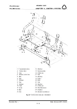
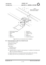
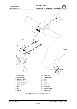
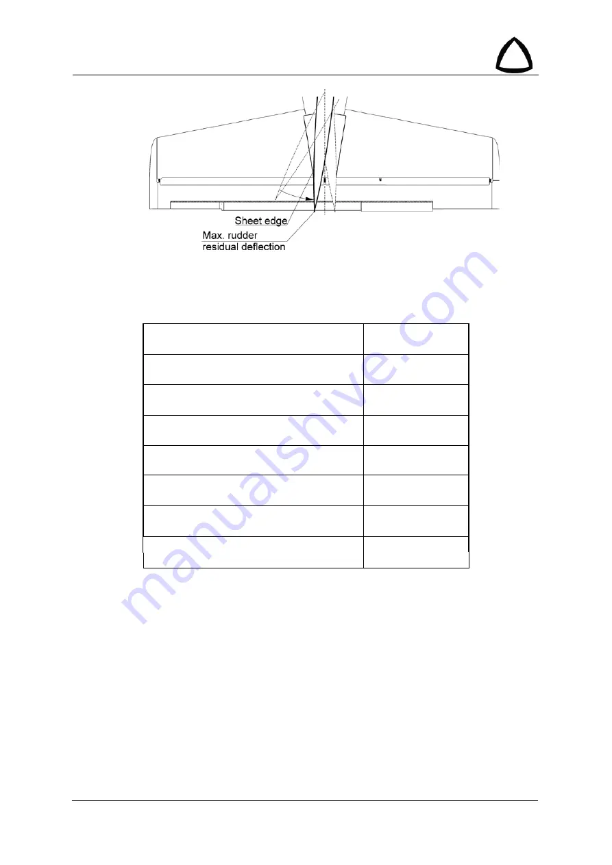
Fig. 6-16
: Friction in directional control system
6.4.3 Check of control surface deflections
Control surface deflections of PS-28 Cruiser are shown in the following table:
Aileron
15° ± 1° up
15° ± 1° down
Rudder
30° ± 2° right
30° ± 2° left
Elevator
24° ± 2° up
24° ± 2° down
Wing flap
0° to 30° ± 1°
Difference between L/R flap deflections
± 0.5°
Elevator trim tab
22° ± 2° up
28° ± 2° down
Elevator balance tab
25° ± 2° up
19° ± 2° down
Aileron trim tab
20° ± 2° up
20° ± 2° down
Tab. 6-1
: Deflections of control surfaces
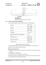
For measuring deflections use protractor with deflecting pointer that will be attached to an
appropriate control surface by means of the clamp.
Measuring aileron deflections
a) Attach the protractor with the deflecting pointer on the upper skin of the aileron by means of
the clamp.
b) Set the aileron to neutral position.
c) Set the protractor to 0° - starting value for measuring.
d) Deflect aileron to the lower (possibly upper) extreme position and read the deflection value.
e) Check deflection values according to the Tab. 6-1.

