background image


ROBOT . HEAD to TOE 


Product User’s Manual – 

MDS40A


4.0 BOARD LAYOUT 


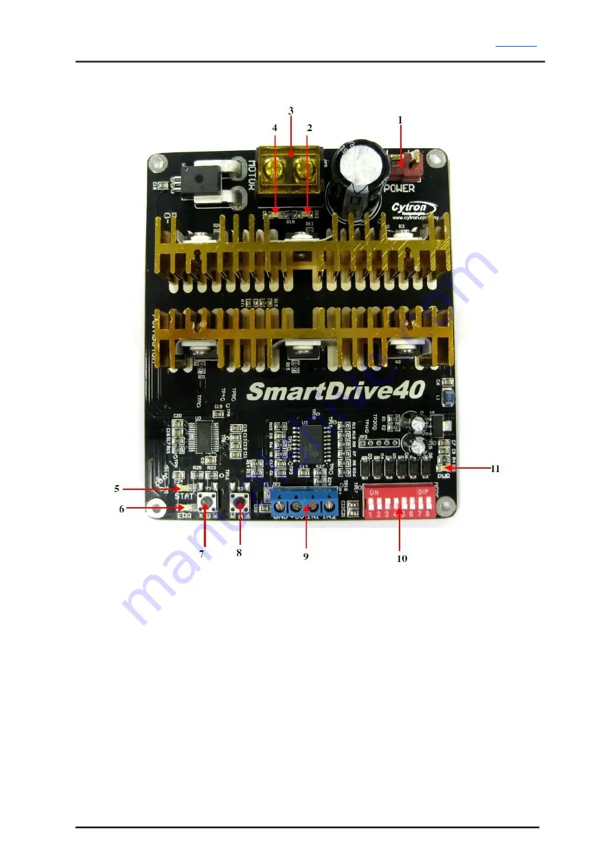
Components on MDS40A and their functions: 
 

1.

Dean T Connector (Male) – Connect to power source. For high current application,


please solder the wire directly to the pad at bottom layer. 
 

2.

LED A – Turns on when the output A is high and output B is low. Indicates the


current flows from output A to B. 


3.

Terminal Block – Connect to motor. Reverse the polarity if the motor direction is


incorrect. 


4.

LED B – Turns on when the output A is low and output B is high. Indicates the


current flows from output B to A. 


5.

LED STAT – Status LED. Turn on when the motor is running. Turn off otherwise. 

Created by Cytron Technologies Sdn. Bhd. – All Rights Reserved


Summary of Contents for MDS40A

Page 1: ...ROBOT HEAD to TOE Product User s Manual MDS40A MDS40A SmartDrive40 User s Manual V1 3 Aug 2014 Created by Cytron Technologies Sdn Bhd All Rights Reserved 1 ...

Page 2: ...Product Specifications 5 4 Board Layout 6 5 Power Supply 8 6 Motor Connection 15 7 Safety Features 19 8 Input Modes 20 8 1 RC Input Mode 21 8 2 Analog PWM Input Mode 24 8 3 Simplified Serial Mode 29 8 4 Packetized Serial Mode 30 9 Warranty 32 Created by Cytron Technologies Sdn Bhd All Rights Reserved 2 ...

Page 3: ... up with another similar unit and operates in pair This make driving a robot with differential drive a truly plug and play experience Some of the features for SmartDrive40 are summarized as below Bi directional control for a single brushed DC motor Support motor from 7V to 25V Maximum current up to 80A peak 1 second 40A 5 minutes or 30A 20 minutes continuously 16 KHz switching frequency for quiet ...

Page 4: ...ing to the packing lists If there are any parts missing please contact us at sales cytron com my immediately 1 1 x MDS40A SmartDrive40 2 1 x Dean T Connector Female 3 User s manual and sample source code can be downloaded from http www cytron com my Created by Cytron Technologies Sdn Bhd All Rights Reserved 4 ...

Page 5: ...es 20 minutes 40 30 A A 3 I PEAK Peak Motor Current 80 A 4 V IOH Logic Input High Level 3 5 5 V 5 V IOL Logic Input Low Level 0 0 0 5 V 6 5V Output Current 50 mA Depends on the room temperature Must not exceed 1 second Not applicable for PWM signal as PWM signal will be converted to analog voltage via low pass filter before processed by the processor Created by Cytron Technologies Sdn Bhd All Righ...

Page 6: ...LED A Turns on when the output A is high and output B is low Indicates the current flows from output A to B 3 Terminal Block Connect to motor Reverse the polarity if the motor direction is incorrect 4 LED B Turns on when the output A is low and output B is high Indicates the current flows from output B to A 5 LED STAT Status LED Turn on when the motor is running Turn off otherwise Created by Cytro...

Page 7: ...ed current flows from output B to A and motor will turn CCW or CW depending on the connection 8 Test Button A When this button is pressed current flows from output A to B and motor will turn CW or CCW depending on the connection 9 Input Pin No Pin Name Description 1 IN2 Input channel 2 2 IN1 Input channel 1 3 5V 5V output Do not connect to another 5V source 4 Gnd Ground Warning The 5V output is de...

Page 8: ...y the input voltage will rise when the driver is regenerating motor is slowing down Thus it is important to connect a battery with same voltage in parallel with the power supply to absorb the current generated by the motor Else the input voltage might rise to a level where SmartDrive40 will be destroyed permanently 2 For application where the current is 20A it s recommended to solder the wire dire...

Page 9: ...l MDS40A 2 Cut and remove the wire insulator If user needs to solder the wire directly from battery to Dean T connector solder one terminal at a time and leave another one wrapped Created by Cytron Technologies Sdn Bhd All Rights Reserved 9 ...

Page 10: ...h Slide in the shrinking tube into the wire The shrinking tube is used to protect the connection at the Dean T terminal 4 Solder the wire to Dean T connector Be careful while soldering and make sure the polarity is correct Created by Cytron Technologies Sdn Bhd All Rights Reserved 10 ...

Page 11: ... with shrinking tube and supply heat to it The shrinking tube will shrink and cover the connection neatly as shown below User may use soldering iron to heat the shrinking tube 6 Continue with another terminal Created by Cytron Technologies Sdn Bhd All Rights Reserved 11 ...

Page 12: ... pad at bottom layer are shown below 1 Identify the polarity of power terminal There are and marking at the bottom layer of MDS40A 2 Cut and remove the wire insulator Solder one terminal at a time and leave another one wrapped Created by Cytron Technologies Sdn Bhd All Rights Reserved 12 ...

Page 13: ...ser s Manual MDS40A 3 Solder the wire to the pad at the bottom layer Be careful while soldering and make sure the polarity is correct 4 Continue with another terminal Created by Cytron Technologies Sdn Bhd All Rights Reserved 13 ...

Page 14: ...ROBOT HEAD to TOE Product User s Manual MDS40A 5 Below is an example of power cable being soldered directly to the bottom layer Created by Cytron Technologies Sdn Bhd All Rights Reserved 14 ...

Page 15: ...d directly to the bottom layer pad NOTE For application where the current is 20A it s recommended to solder the wire directly to the pad at bottom layer Steps to connect the motor via terminal block 1 Open the cover for terminal block 2 Remove the screw from the terminal block 3 Wrap the wire of DC motor around the screw Created by Cytron Technologies Sdn Bhd All Rights Reserved 15 ...

Page 16: ...AD to TOE Product User s Manual MDS40A 4 Put back the screw into terminal block and tighten the screw 5 Repeat step 2 4 for another wire of DC motor Created by Cytron Technologies Sdn Bhd All Rights Reserved 16 ...

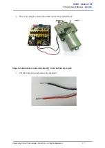
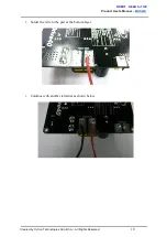
Page 17: ...DS40A 6 This is an example connection of DC motor via terminal block Steps to solder motor connection directly to the bottom layer pad 1 Cut the motor wire and remove the insulator Created by Cytron Technologies Sdn Bhd All Rights Reserved 17 ...

Page 18: ...BOT HEAD to TOE Product User s Manual MDS40A 2 Solder the wire to the pad at the bottom layer 3 Continue with another terminal as shown below Created by Cytron Technologies Sdn Bhd All Rights Reserved 18 ...

Page 19: ...attery to avoid further damage to the battery If the other type of battery is used to power the board the LiPo under voltage warning will still be shown In this case user may ignore the warning and he she needs to estimate when to replace the battery by him herself c Over Current Protection Error LED blinks 4 times If over current is detected for more than 1 second the current limiting feature wil...

Page 20: ...t mode The DIP switch settings for each mode and the function for input pin are summarized as below Input Mode DIP Switch SW1 SW4 DIP Switch SW5 SW8 Description Input 1 Input 2 RC 0000XXXX SW5 6 SW7 SW8 Single Mix Mode 0X Single 10 Mix Left 11 Mix Right Exponential Mode MCU Mode Speed Steering Mix Mode only Analog PWM XX01XXXX SW1 2 SW5 6 SW7 SW8 Analog PWM Mode 00 Analog 11 PWM Single Mix Mode 0X...

Page 21: ... the right motor of the robot differential drive system Input 1 controls the overall speed as well as forward backward movement of the robot Input 2 controls the left right or pivot movement of the robot In right mix mode the motor will be slowed down when the robot is commanded to turn right and vice versa Exponential Mode SW7 0 1 Off The speed is linear with the input signal This is for low to m...

Page 22: ...itch Mode 00000000 RC Mode Single Channel Mode Exponential Off MCU Mode Off 00000010 RC Mode Single Channel Mode Exponential On MCU Mode Off 00001000 RC Mode Left Mix Mode Exponential Off MCU Mode Off 00001100 RC Mode Right Mix Mode Exponential Off MCU Mode Off Created by Cytron Technologies Sdn Bhd All Rights Reserved 22 ...

Page 23: ...Manual MDS40A Figures below show the connection in RC mode for Single Channel Mode Input 1 is connected to either a RC Receiver or a microcontroller generating the RC pulse Created by Cytron Technologies Sdn Bhd All Rights Reserved 23 ...

Page 24: ...Channel Mode The motor speed and direction are controlled by a single channel connected to Input 1 Motor stops when the input signal is at the center point Input 2 is not used in this mode Left Mix Mode This mode should be selected for the left motor of the robot differential drive system Input 1 controls the overall speed as well as forward backward movement of the robot Input 2 controls the left...

Page 25: ...reference only Actual side of the motor may depends on the Input signal Table below shows the commonly used DIP switch settings for Analog PWM mode DIP Switch Mode 00010000 Analog Mode Single Channel Mode Exponential Off Sign Magnitude Mode Off 10010001 PWM Mode Single Channel Mode Exponential Off Sign Magnitude Mode On 11011000 PWM Mode Left Mix Mode Exponential Off Sign Magnitude Mode Off 110111...

Page 26: ...ROBOT HEAD to TOE Product User s Manual MDS40A Figure below shows the connection of Analog PWM mode for Single Channel Mode ...

Page 27: ... for two units of SmartDrive40 as shown below 2 Set the DIP Switch to operate in RC mode Driver for left motor must be set as left mix mode and driver for right motor must be set as right mix mode Exponential can be turned on or off for both motor but both motor must have the same exponential setting MCU mode should be turned off for both motor DIP switch setting for Left Mix Mode 00001000 Exponen...

Page 28: ...me time The left motor should run slower than the right motor If this is not so power off the SmartDrive40 and change the DIP switch setting of mixing side for both motor After that start from step 1 again iv Push the direction channel stick to right The right motor should run slower than the left motor This means the mixing side of the motor is set correctly v Now we want to make sure the motor d...

Page 29: ...y pulled high and it may be left unconnected if not used A single byte of data is all you need to control the speed and direction of the motor Sending byte 127 stops the motor 0 is full reverse and 255 is full forward Simplified Serial mode is selected by setting SW1 SW2 and SW4 to 0 Down and SW3 to 1 Up SW5 is not used in this mode and SW6 SW8 are used to select the UART baud rate Input Mode SW1 ...

Page 30: ...the header byte the error LED will blink and indicate that there is input error 2 SmartDrive40 may take up to 500ms to start up after power is applied Sending the header byte for auto baud during this time period may cause undesirable results Please allow a one second delay between applying power and sending the header byte Packetized Serial mode is selected by setting SW1 SW2 to 0 Down and SW3 SW...

Page 31: ...ROBOT HEAD to TOE Product User s Manual MDS40A Figure below shows the connection to multiple drivers in Packetized Serial Mode Created by Cytron Technologies Sdn Bhd All Rights Reserved 31 ...

Page 32: ... miss use is not covered under warranty Warranty does not cover freight cost for both ways Prepared by Cytron Technologies Sdn Bhd 19 Jalan Kebudayaan 1A Taman Universiti 81300 Skudai Johor Malaysia Tel 607 521 3178 Fax 607 521 1861 URL www cytron com my Email support cytron com my sales cytron com my Created by Cytron Technologies Sdn Bhd All Rights Reserved 32 ...

Reviews: