background image

PSoC Analog Coprocessor Pioneer Kit Guide, Doc. # 002-11190 Rev. *B

51

A.5

Bill of Materials

BOM file is located in the following path in the kit software installation:

<Install_Directory>\CY8CKIT-048 PSoC Analog Coprocessor Pioneer Kit\1.0
\Hardware\CY8CKIT-048 PCBA BOM.xlsx

Summary of Contents for PSoC CY8CKIT-048

Page 1: ...CY8CKIT 048 PSoC Analog Coprocessor Pioneer Kit Guide Doc 002 11190 Rev B Cypress Semiconductor 198 Champion Court San Jose CA 95134 1709 www cypress com ...

Page 2: ...LITY AND FITNESS FOR A PARTICULAR PUR POSE To the extent permitted by applicable law Cypress reserves the right to make changes to this document without fur ther notice Cypress does not assume any liability arising out of the application or use of any product or circuit described in this document Any information provided in this document including any sample design information or programming code ...

Page 3: ...ronyms 13 2 Software Installation 15 2 1 Before You Begin 15 2 2 Install Software 15 2 3 Uninstall Software 17 3 Kit Operation 18 3 1 Theory of Operation 18 3 2 Flexible Prototyping 32 3 3 KitProg2 Functions 34 4 Code Examples 36 4 1 Using the Kit Code Example 36 4 2 Code Examples 38 A Appendix 39 A 1 Schematics 39 A 2 Hardware Functional Description 39 A 3 Using the FM24V10 F RAM 44 A 4 Migrating...

Page 4: ...of CE as a Class A product General Safety Instructions ESD Protection ESD can damage boards and associated components Cypress recommends that the user perform procedures only at an ESD workstation If an ESD workstation is not available use appropriate ESD protection by wearing an antistatic wrist strap attached to a grounded metal object Handling Boards PSoC Analog Coprocessor Pioneer Kit is sensi...

Page 5: ...om multiple sensors to enable new sensing capabilities commonly known as sensor fusion Sensor fusion solutions often require custom AFEs The PSoC Analog Coprocessor reduces the need for specialized ICs offering the ability to create custom AFEs in a single chip solution Figure 1 1 shows the analog sensors interface on PSoC Analog Coprocessor Pioneer Kit The PSoC Analog Coprocessor Pioneer Kit offe...

Page 6: ...owing PSoC Analog Coprocessor Pioneer board USB Standard A to Mini B cable Four jumper wires 4 inches each Five connectors one 10x1 two 8x1 one 6x1 and one 4x1 One metal disk Quick Start Guide Figure 1 2 Kit Contents Inspect the contents of the kit if you find any part missing contact your nearest Cypress sales office for help www cypress com support ...

Page 7: ...sources USB coin cell or an external power supply Refer to Power Supply System on page 40 for details There is a power selection jumper J9 which allows you to select the kit operating voltage The kit can operate at 1 8 V 3 3 V or 5 V when powered from the USB connector or external power supply and will operate at 3 0 V when powered from the coin cell The USB connector is used as a power source and...

Page 8: ...oard Pinout Table 1 1 Jumpers Switches Default Position Jumper Switch Purpose Default Position J9 System Power VDD Voltage Selection 1 2 3 3V J14 Shunt Selection for Current Measurement 3 4 NO SHUNT J17 Humidity Sensor Calibration 1 2 SENSOR CONNECTED SW4 VDD Source Selection REG SW5 Power Domain Monitor Selection DIGITAL ...

Page 9: ...ammers for PSoC devices For more information visit www cypress com psoccreator PSoC Creator Code Examples PSoC Creator includes a large number of code examples These examples are accessible from the PSoC Creator Start page as shown in Figure 1 6 Code examples can speed up your design process by starting you off with a complete design instead of a blank page The code examples also show how to use P...

Page 10: ...ntroduction Create a new workspace for the code example or add to your existing workspace This can speed up your design process by starting you off with a complete basic design You can then adapt that design to your application Figure 1 6 Code Examples in PSoC Creator ...

Page 11: ... Simple Component Code Examples Choose File Code Example These examples demon strate how to configure and use PSoC Creator Components To access examples related to a specific Component right click on the Component in the schematic or in the Component Catalog Select the Find Code Example option in the context menu that appears System Reference Guide Choose Help System Reference System Reference Gui...

Page 12: ...eets describe and provide electrical specifications for the PSoC 4000 PSoC 4100 PSoC 4200 PSoC 4100M PSoC 4200M PSoC 4200L PSoC 4000S and PSoC Analog Coprocessor device families Getting Started with PSoC Analog Coprocessor provides information on how to get started with PSoC Analog Coprocessor CapSense Design Guide Learn how to design capacitive touch sensing applications with the PSoC 4 and PSoC ...

Page 13: ... entered text and source code C cd icc Italics Displays file names and reference documentation Read about the sourcefile hex file in the PSoC Creator User Guide Bracketed Bold Displays keyboard commands in procedures Enter or Ctrl C File Open Represents menu paths File Open New Project Bold Displays commands menu paths and icon names in procedures Click the File icon and then click Open Times New ...

Page 14: ...it PCB Printed Circuit Board PGA Programmable Gain Amplifier PIR Pyroelectric Infrared PPTC Polymeric Positive Temperature Coefficient PRB Programmable Reference Block PSoC Programmable System on Chip PWM Pulse Width Modulation RGB Red Green Blue SAR Successive Approximation Register SCB Serial Communication Block SNR Signal to Noise Ratio SPI Serial Peripheral Interface SRAM Serial Random Access ...

Page 15: ... ages If these packages are not on your computer the installer directs you to download and install them from the Internet b CY8CKIT 048 Kit Only This executable file installs only the kit contents which include kit code examples hardware files and user documents This package can be used if all the soft ware prerequisites listed in step 5 are installed on your PC c CY8CKIT 048 DVD ISO This file is ...

Page 16: ...oprocessor Pioneer Kit related files Choose the directory and click Next 5 When you click Next the installer automatically installs the required software if it is not present on your computer The following are the required software a PSoC Creator 3 3 Component Pack 3 CP3 or later This software is available separately from www cypress com psoccreator b PSoC Programmer 3 24 2 or later This is instal...

Page 17: ...e installation is complete the kit contents are available at the following location Install_Directory CY8CKIT 048 PSoC Analog Coprocessor Pioneer Kit Default location Windows 7 64 bit C Program Files x86 Cypress CY8CKIT 048 PSoC Analog Coprocessor Pioneer Kit Windows 7 32 bit C Program Files Cypress CY8CKIT 048 PSoC Analog Coprocessor Pioneer Kit Note For Windows 7 8 8 1 10 users the installed fil...

Page 18: ...agram of the PSoC Analog Coprocessor block See PSoC Analog Coprocessor on page 20 for more details on the feature set The analog sensors block consists of five onboard sensors They are PIR motion sensor ambient light sensor thermistor inductive proximity sensor and humidity sensor The output of the analog sensors is fed to the PSoC Analog Coprocessor block Figure 3 2 shows the block diagram of the...

Page 19: ...AM SPI Header 3x2 Arduino Compatible I O Headers to baseboard Arduino Compatible I O Connectors to shield General Purpose I O Headers to baseboard General Purpose I O Connectors to shield KitProg2 PSoC 5LP Reset Button PSoC Analog Coprocessor PIR Motion Sensor Thermistor Inductive Proximity Sensor Ambient Light Sensor I2C UART SPI SWD 3 3V VDD Signal bus Power Signal Analog Sensors Humidity Sensor...

Page 20: ...Shield 5V 3V Coin cell Arduino Compatible Power Header to baseboard Arduino Compatible Power Header to shield 3 3V 1 8 3 3V 5V 3 3V 5V Reset VIN VDD Voltage Selection jumper VDD Resettable Fuse Regulator ON OFF control Power Signal Programmable Interconnect and Routing GPIO Smart I O x8 PSoC Analog Coprocessor SCB x3 TCPWM x8 12 bit SAR Universal Analog Block CMP x2 I O Subsystem Programmable Anal...

Page 21: ...opamp circuits Can use an internal resistor array to form a programmable gain amplifier PGA with gain up to 32 6 MHz gain bandwidth when driving external I Os with up to 10 mA drive 8 MHz gain bandwidth when driving internal nodes such as the SAR ADC 1 mV input offset voltage 15 µA operating current in Deep Sleep mode Two low power comparators CMP Wake up the device from low power modes 12 bit SAR...

Page 22: ...ns A single 8 bit IDAC can be created by combining the two IDACs in parallel 37 5 nA LSB current for precise capacitance measurements Six output current ranges 4 76 µA to 609 µA in source or sink configuration 32 bit Signal Processing Engine ARM Cortex M0 CPU operating at up to 48 MHz Up to 32 KB of flash with read accelerator Up to 4 KB of SRAM 8 channel direct memory access DMA controller Watch ...

Page 23: ...trum that falls between microwaves and visible light Infrared radiation has wavelengths longer than the visible light but shorter than microwaves Humans at normal body temperature radiate strongest in the infrared range at an approximate wavelength of 10 µm The PIR motion sensor uses infrared sensitive materials as the sensing elements It is packaged with a field effect transistor FET in the Sourc...

Page 24: ...gure 3 7 shows the dual element PIR motion sensor with the elements connected in series but with an opposite phase because of which it has the maximum sensitivity along a particular axis Figure 3 7 PIR Motion Sensor Dual Element The sensor package is designed to have a unique field of view for each element When an IR radiating source moves across the fields of view the sensor generates a different...

Page 25: ... the amplification of the input offset voltage Thus a two stage amplifier is best suited for amplifying with a high gain The total gain is split between two stages The first stage amplifier uses a noninverting amplifier configuration using an internal opamp and external gain setting resistors R118 and R119 The second stage amplifier uses a PGA Component The first stage amplifier gain is set to 681...

Page 26: ...ge is independent of supply voltage fluctuations and hence provides a stable voltage reference This volt age is generated using the programmable reference Component PVref and is buffered using an opamp The output of the TIA is measured using the 12 bit Scanning SAR ADC Component with the positive input connected to the TIA output and the negative input connected to the reference voltage of the TIA...

Page 27: ...supply voltage fluctuations and hence provides a stable voltage reference This voltage is generated using the programmable reference Component PVref and is buffered using an opamp The same bandgap voltage is used as the ADC reference This enables measurement in the full scale range of the ADC and results in increased resolution of voltage measurement Three voltage signals Vtherm Vlow and Vhi from ...

Page 28: ... PSoC Analog Coprocessor Pioneer Kit consists of six stages a sensor excitation circuit a tank circuit a high pass filter HPF a down mixer a rectifier and an ADC The main stages of the inductive proximity sensing implementation PWM of sensor excitation circuit down mixer rectifier and ADC are implemented in the PSoC Analog Coprocessor Figure 3 13 shows the PSoC Creator schematic for inductive prox...

Page 29: ...e Proximity Sensor For details of firmware implementation refer to the Code Example CE211252_Inductive_Proximity_ Sensing available in the kit installation directory 3 1 2 5 Interfacing with a Humidity Sensor Humidity can be measured by measuring the capacitance of a capacitive humidity sensor A Cypress CapSense Component is used to measure the capacitance of the humidity sensor The CapSense Compo...

Page 30: ...hen the humidity sensor is being measured RawCountCref is the raw count obtained from the CapSense Component when the reference capaci tor is being measured RawCountcos is the raw count that corresponds to the offset capacitance trace capacitance with sensor disconnected COS is the offset capacitance trace capacitance with sensor disconnected from the pin Humidity is calculated from the measured c...

Page 31: ...rol with high accuracy high bandwidth and high flexibility Analog capability spans the range from thermocouples near DC voltages to ultra sonic signals For more information refer to the KitProg2 User Guide visit the PSoC 5LP web page and refer to the CY8C58LPxx Family Datasheet 3 1 4 Power Supply The power supply system is designed to support 1 8 V 3 3 V or 5 V operation when supplied from the ext...

Page 32: ...m the sensor by removing the corresponding 0 resistor Figure 3 15 Connection Between Sensors Port Pins and Headers Table 3 3 List of 0 Resistors Connecting PSoC Pins to Sensors and Headers Pin Sensor Where on Sensor Circuit 0 for sensor Header 0 for header P2 0 PIR motion sensor HPF at output of PIR sensor R54 J6 9 R143 P2 1 PIR motion sensor Feedback resistor for first stage Amplifier R131 J2 9 R...

Page 33: ...igure 3 16 Figure 3 16 Sensor and Header Pin Connections P3 4 Inductive proximity sensor Output of LPF R126 J2 5 R125 P0 2 Inductive proximity sensor Series resistor of Inductive sensor R128 J6 1 R129 P1 5 Humidity sensor Connector J17 N A J17 J4 3 R155 P1 7 Humidity sensor Reference capacitor R133 J3 2 R10 Table 3 3 List of 0 Resistors Connecting PSoC Pins to Sensors and Headers continued Pin Sen...

Page 34: ...mming and Debugging Using PSoC Creator 1 Connect the PSoC Analog Coprocessor Pioneer Kit to the PC using the USB cable as shown in Figure 3 17 You can proceed to the next step if you see the amber status LED turned ON the green and red status LEDs turned OFF and the power LED is turned ON If you do not see the desired LED status see the KitProg2 User Guide for details on the KitProg2 status and tr...

Page 35: ...RT bridge UART lines between PSoC Analog Coprocessor and KitProg2 are hard wired on the board with UART_RX assigned to P0 5 and UART_TX assigned to P0 4 of the PSoC Analog Coprocessor For more details on the KitProg2 USB UART functionality see the KitProg2 User Guide Figure 3 18 UART Connection Between KitProg2 and PSoC Analog Coprocessor 3 3 4 USB I2C Bridge The KitProg2 can function as a USB I2C...

Page 36: ... code examples visit the PSoC 3 PSoC 4 and PSoC 5LP code examples page which lists all PSoC Creator code examples available across application notes kits and PSoC Creator 4 1 Using the Kit Code Example Follow these steps to open and use the code examples 1 Launch PSoC Creator from Start All Programs Cypress PSoC Creator version PSoC Creator version 2 On the Start page expand CY8CKIT 048 under Exam...

Page 37: ...ll complete automatically the result will appear in the PSoC Creator status bar at the bottom left side of the screen If the device is yet to be acquired the Select Debug Target window will appear Select KitProg2 serial number and click the Port Acquire button as shown in Figure 4 2 Figure 4 2 Port Acquire 8 After the device is acquired it is shown in a tree structure below KitProg2 serial number ...

Page 38: ...easure the thermistor resistance and calculate the temperature The measured thermistor resistance and the calculated temperature are sent over I2C The RGB LED is controlled based on the calculated temperature value 4 CE211305 Inductive Proximity Sensing This code example demonstrates how to interface PSoC Analog Coprocessor with an inductive proximity sensor The code example measures the change in...

Page 39: ...ontains firmware controlled resistive pull ups using FETs which can be enabled or disabled using PSoC 5LP pins The USB Serial pins of the PSoC 5LP device are also available on the Arduino compatible header therefore the PSoC 5LP device can be used to control Arduino shields with an SPI I2C UART interface Note KitProg2 firmware does not support the USB SPI bridge functionality at present SPI pins o...

Page 40: ... or a programmable voltage level 1 8 V 3 3 V VDD source selection slider switch SW4 is used to select the power supply from the voltage regulator USB or the 3 V coin cell Power Supply Input Voltage Range for VIN is 6 12V Regulator Power Selection SHORT 3 2 SHORT 4 2 O P VOLTAGE JUMPER SETTING VOLTAGE SELECTION JUMPER SETTINGS 1 8V 5 0V 3 3V REMOVE JUMPER MODE SHORT 1 2 1 8V 3 3V PROGM MANUAL MANUA...

Page 41: ...ion of the PSoC Analog Coprocessor using its internal Del Sig ADC and SAR ADC For this purpose either a 1 Ohm shunt resistor or 10 Ohm shunt resistor can be selected using the jumper J14 Connect an ammeter between terminals 3 and 4 of the jumper J14 to measure the PSoC Analog Coprocessor current consumption manually Figure A 4 shows the detailed circuit for analog digital power monitoring Figure A...

Page 42: ... on the PSoC Analog Coprocessor Pioneer Kit A 2 5 3 PSoC 5LP GPIO Header J16 An 8 2 header is provided on the board to bring out several pins of the PSoC 5LP device to support advanced features such as a low speed oscilloscope and a low speed digital logic analyzer This header also contains USB UART bridge pins and USB I2C bridge pins that can be used when these pins are not accessible on Arduino ...

Page 43: ...he I2C slave address of the F RAM device is 7 bits wide and the two least significant bits are configurable through physical pins These pins are hard wired to 00 on the board By default the address of the F RAM device used on the kit is 0x50 This address can be modified by changing the R44 R39 and R36 R37 resistor pairs The operating voltage range of the F RAM is between 2 V and 3 6 V To prevent t...

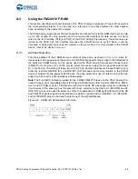
Page 44: ...provided in the datasheet of the particular F RAM device For the device used on the PSoC Analog Coprocessor Pioneer board FM24V10 G the slave ID is 1010b Device select bits are set using the two physical pins A2 and A1 in the device The setting of these two pins in PSoC Analog Coprocessor Pioneer board is con trolled by resistors R44 R39 A1 and R36 R37 A2 Because the memory location in the F RAM d...

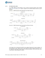
Page 45: ...igh speed mode A master code 00001XXXb must be issued to place the device into high speed mode Communication between the master and the slave will then be enabled for speeds up to 3 4 MHz A STOP condition will exit the Hs mode Single and mul tiple byte reads and writes are supported Figure A 6 F RAM I2C Data Format for HS Mode ...

Page 46: ...ick reference Figure A 7 F RAM Single Byte and Multiple Byte Write Packet Structure Figure A 8 F RAM Single Byte and Multiple Byte Read Packet Structure As the figures show operations start with the slave address followed by the memory address For write operations the bus master sends the slave address and memory address followed by one or more data bytes Each byte of data is written to consecutiv...

Page 47: ...es with the PSoC Analog Coprocessor family A 4 Migrating Projects Across Different Pioneer Series Kits Cypress Pioneer series kits are Arduino Uno compatible and have some common onboard peripher als such as RGB LED CapSense and User Switch However the pin mapping in each of the boards is different due to differences in pin functions of the PSoC device used This section lists the pin mapping of th...

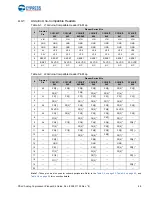
Page 48: ...IOREF P4 VDD P4 VDD BLE VDD P4 VDD P4 VDD P4 VDD PAC VDD 8 NC NC NC NC NC NC NC NC Table A 2 J2 Arduino Compatible Header Pin Map Arduino Pin Pioneer Series Kits CY8CKIT 042 CY8CKIT 040 CY8CKIT 042 BLE CY8CKIT 044 CY8CKIT 046 CY8CKIT 041 CY8CKIT 048 1 A0 P2 0 P0 0 P3 0 P2 0 P2 0 P2 0 1 P3 0 2 P0 2 1 P2 0 P2 6 1 P3 6 1 P1 6 1 3 A1 P2 1 P0 1 P3 1 P2 1 P2 1 P2 1 P3 1 4 P0 3 1 P2 1 1 P6 5 1 P3 7 1 P4 ...

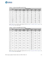
Page 49: ...0 7 4 D11 P3 0 P1 1 1 P0 0 P6 0 P6 0 P1 0 1 P0 4 5 D12 P3 1 P3 1 P0 1 P6 1 P6 1 P1 1 1 P0 5 6 D13 P0 6 P1 7 P0 3 P6 2 P6 2 P1 2 1 P0 6 7 GND GND GND GND GND GND GND GND 8 AREF P1 7 NC VREF P1 7 VREF P1 7 1 P1 3 1 9 SDA P4 1 P1 3 P3 4 P4 1 P4 1 P3 1 P4 1 10 SCL P4 0 P1 2 P3 5 P4 0 P4 0 P3 0 P4 0 Table A 4 J4 Arduino Compatible Header Pin Map Arduino Pin Pioneer Series Kits CY8CKIT 042 CY8CKIT 040 C...

Page 50: ...LE CY8CKIT 044 CY8CKIT 046 CY8CKIT 041 CY8CKIT 048 1 Red P1 6 P3 2 P2 6 P0 6 P5 2 P3 4 P1 4 2 Green P0 2 P1 1 P3 6 P2 6 P5 3 P2 6 P2 6 3 Blue P0 3 P0 2 P3 7 P6 5 P5 4 P3 6 P1 6 Table A 6 User Switch Pin Map Arduino Pin Pioneer Series Kits CY8CKIT 042 CY8CKIT 040 CY8CKIT 042 BLE CY8CKIT 044 CY8CKIT 046 CY8CKIT 041 CY8CKIT 048 1 SW2 P0 7 P2 7 P0 7 P0 7 P0 7 P0 3 ...

Page 51: ...Kit Guide Doc 002 11190 Rev B 51 A 5 Bill of Materials BOM file is located in the following path in the kit software installation Install_Directory CY8CKIT 048 PSoC Analog Coprocessor Pioneer Kit 1 0 Hardware CY8CKIT 048 PCBA BOM xlsx ...

Page 52: ...hapter on page 15 Updated Install Software on page 15 Updated description Updated Kit Operation chapter on page 18 Updated Theory of Operation on page 18 Updated description Updated Analog Sensors on page 23 Updated Table 3 1 Updated details in Sensor Part column corresponding to Thermistor and Humidity sensor Updated Interfacing with a PIR Motion Sensor on page 23 Updated description Updated Inte...

Page 53: ...tails in 0 for sensor column corresponding to P1 0 and P1 5 pins Updated details in Header column for all pins Updated details in 0 for header column corresponding to P1 3 pin Updated Programming and Debugging Using PSoC Creator on page 34 Updated description Updated Code Examples chapter on page 36 Updated description Updated Using the Kit Code Example on page 36 Updated description CY8CKIT 048 P...

Page 54: ...ding Updated description Updated USB Mini B Connector on page 42 Updated description Updated Push Buttons on page 43 Updated description Updated Cypress Ferroelectric RAM F RAM on page 43 Updated description Updated External Crystals on page 43 Updated description Updated Using the FM24V10 F RAM on page 44 Updated Address Selection on page 44 Updated description Updated Migrating Projects Across D...

Reviews: