


CY8CKIT-017 CAN/LIN Expansion Board Kit Guide, Doc. # 001-57814 Rev. *D
25
Hardware
is useful if you want to power up other CAN nodes through the CAN connector or if you want to
power up the DVK and EBK from the power supply of some other CAN node.
Warning: Take extra care when populating the CANEXTPWR jumper. The DVK or EBK can be
damaged if the DVK and EBK have their own power supply powering the VIN rail and a different
power supply is connected through pin 9 of the CAN connector.
4.2.3
CAN Bus Termination
The CAN specification requires that CAN nodes located physically at the end of the CAN bus must
terminate the CAN differential signals with 120
. The EBK features a 120-
termination resistor
(R6) that can be enabled or disabled by using jumper JP2. If JP2 is populated, the termination
resistor is active. If JP2 is not populated, the termination resistor is not active.
The termination resistor is active (JP2 is populated) by default.
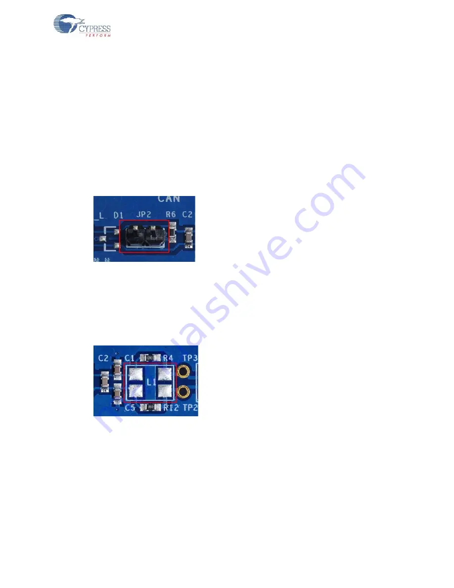
Figure 4-2. JP2 Jumper
4.2.4
Choke Footprint
A footprint for a common-mode signal suppression choke is available on the expansion board, but it
is not populated. This footprint can be populated with a B82789C0 (or equivalent) choke to suppress
common-mode signals on the CAN bus. If a choke component is mounted on the L1 footprint,
resistors R4 and R12 must be removed from the board. The choke component has no effect if these
two resistors are not removed.
Figure 4-3. CAN Choke Footprint
4.2.5
CAN Circuit Isolation
The CAN circuit can be completely isolated from the rest of the CY8CKIT-001 DVK by removing
resistors R3, R5, and R10. Each of these resistors is 0
. This is useful if the CAN circuit is not
needed, but other circuits on the EBK are. In this case, isolating the CAN circuit ensures that the
CAN circuit does not interfere with any other circuits that share the same pins. The footprints for R3,
R5, and R10 are designed so that they can be reconnected easily with a ‘solder jumper’ instead of
repopulating the footprints with a 0-
resistor.


