30
CY3274 Cypress High Voltage Programmable PLC Development Kit Guide, Doc. # 001-53598 Rev. *G
Kit Operation and PLC Control Panel GUI
In GUI B, under the Messaging tab, select the Enable Auto Reception. The message should appear
in the Message Status window.
3.3.2.1
Additional Options
■
Check Infinite Write in A and then click Write Message. The same message is transmitted
continuously until the Infinite Write is unchecked.
■
Set the Write Count to a value greater than 1. Click Write Message. This is the number of times
the same message is sent by A to B.
■
Set the message type to Instant Message. The Payload field now accepts ASCII characters. Type
any message in the field and click Write Message. The message appears on B as text. The setup
works similar to an instant messenger.
■
To send messages in both directions, set up the parameters in B similar to the setting for A
described earlier.
■
Select the Enable Auto Reception in A. Now messages may be sent bi-directionally by typing in
the message in the Payload field and clicking the Write Message button.
■
The remote node configurations are retrieved and set in the Remote Node tab. To get the
configurations, set the address and click Get Configuration. To change the configurations, make
the changes in the corresponding fields and click Set Configuration.
3.3.3
PLC Control Panel Tabs
3.3.3.1
Main Menu Tab
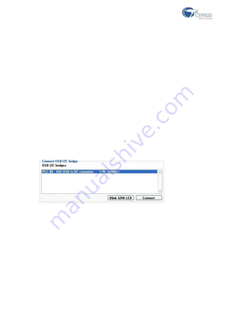
Connect CY3240 USDB-I2C Bridge
Figure 3-9. Connect USB-I2C Bridge
Blink GRN LED
This button blinks the green LED on the bridge to help identify which bridge is currently selected.
Connect
Click Connect to connect the PLC device to the computer. If you try to connect to a bridge that is not
connected to a PLC device, you see an error message. The power mode, slave address, and clock
rate are set according to the selections made in the radio buttons.
Note
If the USB-I2C bridge is powered by external power (that is, a jumper is connected across the
‘PWR’ pin on the PLC board), do not 5 V power as the power mode.


