background image

1

CVX-OPTW_MAN_191216

Cypress Integration Solutions      35+ Years of Access Control Ingenuity      CypressIntegration.com 

© 2019 Cypress Computer Systems     1778 Imlay City Road, Lapeer, MI 48446      800-807-2977 

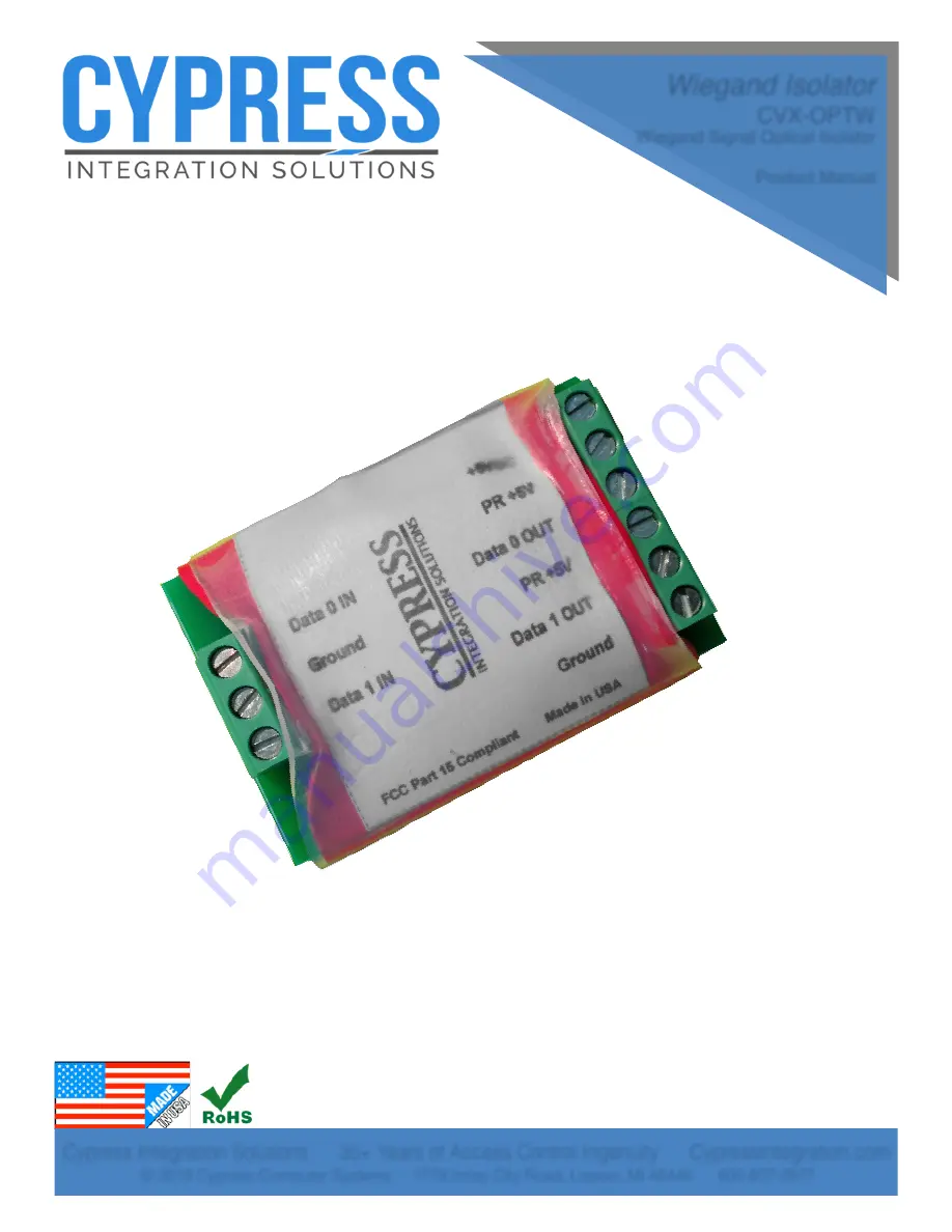
Wiegand Isolator

CVX-OPTW

Wiegand Signal Optical Isolator

Product Manual

Summary of Contents for CVX-OPTW

Page 1: ...ntegration Solutions 35 Years of Access Control Ingenuity CypressIntegration com 2019 Cypress Computer Systems 1778 Imlay City Road Lapeer MI 48446 800 807 2977 Wiegand Isolator CVX OPTW Wiegand Signal Optical Isolator Product Manual ...

Page 2: ...e Reader to One Panel Wiring Diagram 6 The CVX OPTW is designed to provide isolation between different Wiegand sources The input side J1 and output side J2 are electrically isolated using optical couplers to transmit the Wiegand signal from the input side to the output side of the CVX OPTW There are three main applications in which the CVX OPTW is used 1 Connecting two Wiegand readers to one access...

Page 3: ...W Bench Testing When installing the CVX OPTW with new access control equipment bench testing is recommended Refer to the wiring diagrams on pages 4 5 and 6 find the wiring diagram that matches your application and set up a bench test accordingly In many applications the access control equipment is already installed and a bench test is not practical In these applications install the CVX OPTW with t...

Page 4: ...2 and the access control panel while passing the Wiegand signals from both readers to the access control panel Reader 1 Power Ground LED IN Data 1 Data 0 5V DC Power Supply Power Ground Ground LED Out Data1 Data 0 N O COM Access Control Panel Reader 2 Power Ground LED IN Data 1 Data 0 12V DC Power Supply Power Ground 12V DC Power Supply Power Ground Data 1 IN Ground Ground Data 0 IN 5VDC PR 5V Dat...

Page 5: ... Access Control Panel 1 from Access Control Panel 2 while passing the Wiegand signals to both access control panels Reader Power Ground LED IN Data 1 Data 0 5V DC Power Supply Power Ground Ground LED Out Data1 Data 0 N O COM Access Control Panel 2 12 VDC Power Supply Power Ground Ground LED Out Data1 Data 0 N O COM Access Control Panel 1 Data 1 IN Ground Ground Data 0 IN 5VDC PR 5V Data 0 OUT PR 5...

Page 6: ...ol panel using the CVX OPTW to electrically isolate the reader from the access control panel Reader Power Ground LED IN Data 1 Data 0 5V DC Power Supply Power Ground Ground LED Out Data1 Data 0 N O COM Access Control Panel 12 VDC Power Supply Power Ground Data 1 IN Ground Ground Data 0 IN 5VDC PR 5V Data 0 OUT PR 5V Data 1 OUT ...

Page 7: ...d devices that operate at higher voltages If the voltage levels are below 4 4VDC then disconnect the Wiegand device s from the J1 header and measure the devices while they are not connected to anything The J1 header Wiegand inputs are open collector and will be at 0VDC while no devices are connected If the voltage levels of the Wiegand device s are below 4 4VDC while it is not connected to other d...

Reviews: