
3
/900W for CP1500EAVRLCD). If the rated unit capacities are exceeded, an overload
condition may occur and cause the UPS unit to shut down and the circuit breaker to trip.
3.If the power requirements of your equipment are listed in units other than Volt-Amps (VA),
convert Watts (W) or Amps (A) into VA by performing the calculations below. Note: The
equation listed below only calculates the maximum amount of VA that the equipment can
EN
use, not what is typically used by the equipment at given time. Users should expect usage
requirements to be approximately 60% of the maximum power requirements:
Watts (W) x 1.67 = VA or Amps (A) x 230 = VA
Add the totals up for all pieces of equipment and multiply this total by 0.6 to calculate the
approximate requirements.
There are many factors that can affect the amount of power that your computer system will
require. The total load that you will be placing on the battery-powered outlets should not
exceed 80% of the unit's capacity.
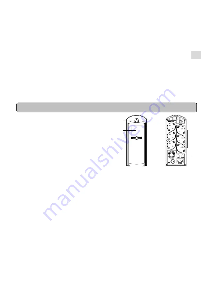
BASIC OPERATION
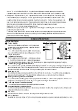
DESCRIPTION
①
Power Switch
Used as the master on/off switch for equipment
connected to the battery power supplied outlets.
②
Power On Indicator
This LED is under the power switch. It illuminates
when the UPS outlets are providing power, free of
surges and spikes.
③
LCD Module Display
High resolution and intelligent LCD display shows
all the UPS information with icons and messages.
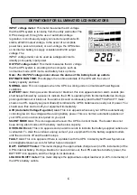
For more information please check the “Definitions for Illuminated LCD Indicators” section.
④
LCD Display Toggle/Selected Switch
The switch can be used to select the LCD display contents including Input Voltage, Output Voltage
and Estimated Run Time. The toggle frequency is set to one time per second. Holding the switch
for more than two seconds while running on battery will silence the buzzer.
⑤
USB Port to PC
The USB port allow communication from the UPS to the computer. The UPS communicates its
status to the PowerPanel
®
Personal Edition software when connected with a USB port.
⑥
Battery and Surge Protected Outlets
The unit has three battery powered/surge protected outlets for connected equipment and ensures
temporary uninterrupted operation of your equipment during a power failure.
⑦
Full-Time Surge Protection Outlets
The unit has three always on surge suppression outlets.
⑧
Communication Protection Ports
Communication protection ports will protect any standard modem, fax, telephone line, broadband
network or Ethernet connection.
⑨
AC Input
Connect the AC Power cord to a properly wired and grounded outlet.
⑩
Circuit Breaker
Located on the side of the UPS, the circuit breaker serves to provide overload and fault protection.
①
②
③
④
⑤
⑧
⑨
⑩
⑦
⑥