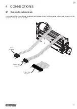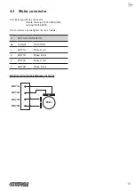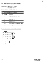
4.2 Thermal head connector
Connector type: JST connector (or equivalent)
male
S15B-PH-K-S
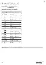
The connector’s pin assignments is as follows:
J5
THERMAL HEAD CONNECTOR
No .
SIGNAL
FUNCTION
1
Vset
Head power supply
2
Vset
Head power supply
3
Vset
Head power supply
4
GND
Ground
5
GND
Ground
6
GND
Ground
7
VDD
Logic power supply
8
TM
Thermistor
9
STB1
Strobe1 signal (Active low)
10
STB2
Strobe2 signal (Active low)
11
STB3
Strobe3 signal (Active low)
12
STB4
Strobe4 signal (Active low)
13
CLK
Serial clock
14
LATCH
Latch (Active low signal)
15
DI
Data input
NOTE: The symbol “ ─── “ means a negative logical signal.
14


