


Page F-17
Repair and Service Manual
B
B
ELECTRONIC SPEED CONTROL
Read all of Section B and this section before attempting any procedure. Pay particular attention to Notices, Cautions, Warnings and Dangers.
CONTROLLER REPLACEMENT
Tool List
Qty.
Socket, 10mm ............................................................. 1
Socket, 7/16" ............................................................... 1
Socket, 13mm ............................................................. 1
Ratchet........................................................................ 1
Extension, 6" ............................................................... 1
Insulated wrench, 9/16"............................................... 1
Shop towel .................................................................. 1
Torque wrench, in. lbs. ................................................ 1
Torque wrench, ft. lbs. ................................................. 1
Large Screwdriver ....................................................... 1
Remove the seat.
Before any electrical service is performed on 48 volt
model vehicles, the Run-Tow/Maintenance switch must
be placed in the ‘Tow/Maintenance’ position.
If a power wire (battery, motor or controller) is discon-
nected for any reason on the 48 volt model vehicle, the
Run-Tow/Maintenance switch must be left in the ‘Tow/
Maintenance’ position for at least 30 seconds after the
circuit is restored.
To prevent electrical shock, the BL- wire must
be removed before discharging the controller
by shorting the B+ and B- terminals of the con-
troller with a large screwdriver. Be sure to hold
screwdriver by the insulated portion.
Using an insulated wrench, remove the BL- wire from
the battery.
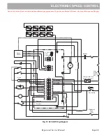
Note the location of the wiring on the controller before remov-
ing wiring from controller. (Ref Fig. 18)
Remove the controller mounting nuts and remove the
controller
.
Mount new controller to mount and reconnect wiring.
Tighten the controller mounting bolts to 108 - 132 in.
lbs. (12 - 15 Nm) torque and the M6 (F1 and F2) bolts to
80 - 90 in. lbs. (9 - 10 Nm) torque and M8 (B+, M-, B-)
bolts to 120 - 130 in. lbs. (14 - 15 Nm) torque.
Replace controller mount assembly in vehicle. Replace
and tighten nuts to 6 - 8 ft. lbs. (8 - 11 Nm) torque.
Reconnect the BL- battery cable and replace the seat.
SOLENOID REPLACEMENT
Tool List
Qty.
Socket, 3/8" ................................................................. 1
Socket, 7/16" ............................................................... 1
Socket, 1/2" ................................................................ 1
Socket, 5/16" .............................................................. 1
Ratchet ........................................................................ 1
Extension, 6" ............................................................... 1
Insulated wrench, 9/16" ............................................... 1
Shop towel................................................................... 1
Torque wrench, in. lbs. ................................................ 1
Torque wrench, ft. lbs. ................................................. 1
Large Screwdriver ....................................................... 1
Remove the seat.
Before any electrical service is performed on 48 volt
model vehicles, the Run-Tow/Maintenance switch must
be placed in the ‘Tow/Maintenance’ position.
If a power wire (battery, motor or controller) is discon-
nected for any reason on the 48 volt model vehicle, the
Run-Tow/Maintenance switch must be left in the ‘Tow/
Maintenance’ position for at least 30 seconds after the
circuit is restored.
To prevent electrical shock, the BL- wire must
be removed before discharging the controller
by shorting the B+ and B- terminals of the con-
troller with a large screwdriver. Be sure to hold
screwdriver by the insulated portion.
Using an insulated wrench, remove the BL- wire from
the battery.
Note the location of the wiring on the solenoid before remov-
ing wiring from solenoid (Ref Fig. 18)
Remove the solenoid mounting bolts and remove the
solenoid
.
NOTICE
NOTICE
Summary of Contents for Shuttle 2
Page 6: ...Page iv Repair and Service Manual NOTES TABLE OF CONTENTS ...
Page 195: ......