background image

GENERAL SPECIFICATIONS

Read all of SAFETY and this section before attempting any procedure. Pay particular attention to Notices, Cautions, Warnings and Dangers.

7

Owner’s Guide

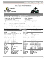
GENERAL SPECIFICATIONS

MODEL: HAULER 800X

TYPE: ELECTRIC 48V POWERED TRUCK
MODEL YEAR: 2015
Part No: 641725

TrueCourse Technology:

Programmable to multiple vehicle terrains, with expanded regenerative braking function, and vehicle charger lockout

z

Solid state continuously variable seperately excited speed controller

z

Six, 8 Volt deep cycle batteries

z

Dash mounted direction selector switch (Forward-Neutral-Reverse)

z

Full torque, reduced speed reverse

z

Anti-roll back, walkaway braking and alarm

z

Inductive throttle sensor

z

Programmable regenerative braking, acceleration and speed

z

Handheld vehicle diagnostics and rounds tracking

Battery Charger:

PowerWise 48VDC high frequency, fully line compensating. 10ft (3m) DC cord. Underwriters Lab. (U.L.) Listed, (C.S.A. Certified)

z

Input:  120 Volts AC, 50/60Hz, 8 amps

z

Output:  48 Volts DC at 13 amps

Motor:

48 Volt DC shunt wound, brazed armature, solid copper windings

Drive Train:

Direct motor shaft connected to transaxle pinion shaft

Electrical System: 

48 Volt DC, six, 8 volt deep cycle batteries (117 minute minimum, 170 amp-hour @ 20 hr. discharge rate)

Transaxle:   

Differential with helical gears

Brakes: 

Dual rear wheel mechanical self-adjusting drum brakes. Automatic single point park brake release with self-compensating system

Cargo Bed:

Roto-molded cross-linked polyethelene. Lifts for access to powertrain. Removable hinged multi-position tailgate requires no latch mechanism

Gear Selection

Dash-mounted Forward-Neutral-Reverse

Overall Length

106.5 in (271 cm)

Rear Axle Ratio

12.44:1

Overall Width

48.5 in (123 cm)

Performance

Overall Height (No Canopy)

49.0 in (126 cm) (top of steering wheel)

Seating Capacity

2 person

Overall Height (With Canopy) 71.6 in (182 cm)

Dry Weight

685 lb (315 kg) (without batteries)

Wheel  Base

65.5 in (166 cm)

Curb Weight

1050 lb (475 kg)

Front Wheel Track

37.0 in (94 cm)

Bed Load Capacity

500 lb (230 kg)

Rear Wheel Track

38.0 in (97 cm)

Vehicle load capacity

800 lb (360 kg)

Gnd Clearance @ Differential 5.5 in (14 cm)

Outside Clearance Circle

18.9 ft (5.76 m)

Cargo Box Width (inside)

44.5 in (113 cm)

Intersecting Aisle Clearance N/A

Cargo Box Length (inside)

30.5 in (77 cm)

Speed (Level Ground)

17 mph ± 0.5 mph (27.3 kph ± 0.8 kph)

Cargo Box Depth (inside)

7.5 in (19 cm)

Towing Capacity

500 lb (230 kg) max load

Cargo Box Capacity

5.9 cu ft (0.17 m3)

Steering & Suspension

Cargo Box material

Roto-molded polyethylene

Steering    

Self-compensating rack and pinion

Vehicle Power

Front Suspension

Leaf springs with hydraulic shock absorbers

Power Source

48 Volts DC

Rear Suspension

Leaf springs with hydraulic shock absorbers

Motor Type

Shunt wound

Service Brake

Rear wheel mechanical self-adjusting drum

Horsepower (kW)

3.0 HP (2.2kW) continuous

Parking Brake

Self-compensating, single point engagement

Electrical System

48 Volt

Front Tires

Turf Saver 20 x 10 - 10 (4 Ply Rated) uni-directional

Batteries (Qty, Type)

Six, 8 Volt deep cycle 

Rear Tires

Turf Saver 20 x 10 - 10 (4 Ply Rated) uni-directional

Key or Pedal Start

Pedal start 

Body & Chassis

Battery Charger

48 VDC PowerWise™ QE, 120 VAC, UL/CSA

Frame

Welded steel with DuraShield™ powder coat

Speed Controller

250 Amp solid state controller

Front Body & Finish

Injection molded TPO

Drive Train

Motor shaft direct drive

Rear Body & Finish

Steel. Base coat/clear coat

Transaxle

Differential with helical gears

Standard Color

Patriot Blue

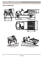
Dimensions

PRODUCT OVERVIEW

CONFIGURATION HIGHLIGHTS

PRODUCT SPECIFICATION


Summary of Contents for Hauler 800XE

Page 1: ...OWNER S GUIDE 642988 B HAULER 800XE REVISED FEBRUARY 2016 ISSUED FEBRUARY 2015...

Page 2: ...ive hand tools If necessary contact your service representative for information about how to service the vehicle as shown in the Periodic Service Schedule Repair or replacement parts are available fro...

Page 3: ...IABILITY FOR INCIDENTAL AND CONSE QUENTIAL DAMAGES resulting from the use of the information and materials in this Manual These are the original instructions as defined by 2006 42 EC CONTACT US E Z GO...

Page 4: ...drain The battery charger can stay connected to the vehicle to keep a full charge on the batteries while the charger is connected to an active electrical supply If the power to the electrical supply i...

Page 5: ...y and Light Switch 11 State of Charge Meter 11 Direction Selector 11 Accelerator Pedal 12 Brake and Parking Brake Pedal 12 Horn 12 Turn Signal Switch if equipped 12 Front Seat 12 Front Hip Restraint 1...

Page 6: ...or Operation 21 Accelerator Pedal Operation 22 Brake and Parking Brake Operation 22 Horn Operation 22 Run Tow Switch Operation 22 Truck Bed Operation 23 Truck Bed Latch Operation 24 Tailgate Operation...

Page 7: ...ORTING VEHICLE 36 Towing 36 Hauling 36 SERVICE AND MAINTENANCE 36 ROUTINE MAINTENANCE 37 TIRE INSPECTION 37 BRAKES 38 Periodic Brake Test 38 REAR AXLE 39 Checking the Lubricant Level 39 LUBRICATION 39...

Page 8: ...ABLE OF CONTENTS Owner s Guide Battery Charging 46 AC Voltage 47 Fault Diagnosis 47 Hydrometer 47 Using A Hydrometer 48 Battery Charger Maintenance 48 PERIODIC SERVICE SCHEDULE PERIODIC SERVICE SCHEDU...

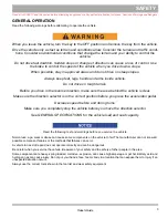
Page 9: ...caused by excessive speed is abusive and will not be covered under the warranty Use caution when you tow the vehicle Towing the vehicle at above the recommended speed can cause personal injury or dama...

Page 10: ...V Anyone who operates this vehicle must be A LICENSED DRIVER AND OPERATE THE VEHICLE ACCORDING TO APPLICABLE STATE REQUIREMENTS This rule is important to the SAFE USE AND OPERATION of the product All...

Page 11: ...tion make sure the area behind the vehicle is clear Make sure the direction selector is in the correct position before you press the accelerator pedal Decrease speed before and during turns Make sure...

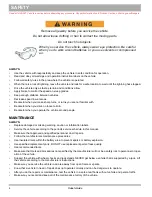
Page 12: ...liar with Be careful when you drive on loose terrain Be careful when you operate the vehicle around people MAINTENANCE ALWAYS Replace damaged or missing warning caution or information labels Service t...

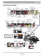
Page 13: ...PACITY MAX INCLINE 14 601781 P F R F 14 25 N 14 25 P P 601781 TO OPERATE VEHICLE TURN KEY TO ON MOVE DIRECTION SELECTOR TO F OR R PRESS ACCELERATOR TO PARK VEHICLE TURN KEY TO OFF MOVE DIRECTION SELEC...

Page 14: ...6 Owner s Guide SAFETY Read all of SAFETY and this section before attempting any procedure Pay particular attention to Notices Cautions Warnings and Dangers Notes...

Page 15: ...ar Axle Ratio 12 44 1 Overall Width 48 5 in 123 cm Performance Overall Height No Canopy 49 0 in 126 cm top of steering wheel Seating Capacity 2 person Overall Height With Canopy 71 6 in 182 cm Dry Wei...

Page 16: ...dure Pay particular attention to Notices Cautions Warnings and Dangers VEHICLE DIMENSIONS RECOMMENDED MAX SIDE TILT 25 or 14o RECOMMENDED MAX RAMP GRADE 25 or 14 MAX o MAX 9 5 in 24 cm 65 5 in 166 cm...

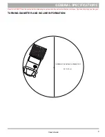
Page 17: ...ad all of SAFETY and this section before attempting any procedure Pay particular attention to Notices Cautions Warnings and Dangers 9 Owner s Guide TURNING DIAMETER AND INCLINE INFORMATION TURNING CLE...

Page 18: ...10 Owner s Guide GENERAL SPECIFICATIONS Read all of SAFETY and this section before attempting any procedure Pay particular attention to Notices Cautions Warnings and Dangers Notes...

Page 19: ...ic electrical system of the vehicle and the lights To prevent accidental operation of an unattended vehicle turn the key to the OFF position and remove from the switch If the vehicle has accessories t...

Page 20: ...ot driven with the park ing brake engaged Pressing the accelerator pedal is not the recommended method to release the parking brake 6 Horn The horn button is found on the driver side of the floorboard...

Page 21: ...A weather enclosure supplies protection from strong weather conditions 16 DC to DC Converter The DC to DC converter supplies power to the power accessories 17 Charger Receptacle Connect the charger c...

Page 22: ...ttery or any other wires move the run tow switch to the TOW position After you connect a battery or any other wires wait a minimum of 30 seconds before you move the switch to the RUN position With the...

Page 23: ...understand and follow the safety label on the instrument panel Make sure you understand how to safely operate the vehicle and its equipment Reckless use of this vehicle can cause severe injury or deat...

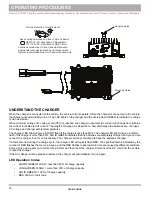
Page 24: ...do not have insulation Disconnect the DC plug before you make or break the connections to a battery that is charging Do not open or disassemble the charger Do not operate the charger if the AC cord i...

Page 25: ...ntal surface with the fins vertical Put the charger on a platform above the ground to allow air to flow around and below the charger If the charger is operated in an outdoor location rain and sun prot...

Page 26: ...eries are completely charged and you can dis connect the charger but it is not necessary The charger can stay connected to keep the batteries charged If a fault occurred during the charge cycle the ch...

Page 27: ...nect the charger DC power cord and connect again If the fault is sensed after that take the charger to an approved service center To decrease the risk of electrical shock or electrocution make sure th...

Page 28: ...SPECIFICATIONS for the vehicle load and seat capacity When the accelerator pedal is pressed the foot operated parking brake releases and can cause accidental or sudden vehicle movement When the vehicl...

Page 29: ...or the direc tion selector to a different position Turn the key to the right to enable the electrical system of the vehicle The first stop is ON and supplies power that allows you to drive the vehicl...

Page 30: ...with the parking brake engaged Pressing the accelerator pedal is not the recom mended method to release the parking brake Brake and Parking Brake Operation The function of the lower part of the brake...

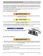
Page 31: ...ou operate the vehicle Read understand and fol low the warning label attached to the front of the load bed Do not allow passengers to ride in the truck bed A sudden move or stop can cause severe injur...

Page 32: ...se caution when you operate the truck bed latch to make sure the truck bed does not accidentally drop during lift or lower procedure If the truck bed drops fingers or other body parts can be trapped T...

Page 33: ...kph option Option 3 Mild Hill This option is the same as the Steep Hill option except that the pedal up braking affect is not as strong This is the 13 8 mph 22 2 kph option Option 4 Freedom This optio...

Page 34: ...he vehicle speed is more than the specified top speed with the accelerator pedal pressed or released the pedal up brake limits the speed of the vehicle to the specified top speed When the regenerative...

Page 35: ...ntroller from the batteries The Electronic Speed Control system has three separate units pedal box speed sensor controller TCT features include regenerative braking pedal up braking walk away anti rol...

Page 36: ...re Anti Stall protection prevents motor damage if the vehicle is stalled against an object or on a hill Example If all of the following events occur the system senses that the accelerator pedal is pre...

Page 37: ...the accelerator pedal is released the motor decreases the speed of the vehicle To stop the vehicle quickly press the brake pedal When the direction selector is in the reverse position a warning signal...

Page 38: ...uide Coasting Do not allow the vehicle to coast at above recommended speeds Control vehicle speed with the brake The vehicle has a braking feature pedal up that decreases the speed when the accelerato...

Page 39: ...r soft brush to clean the vinyl seats and plastic or rubber trim Dry with a cloth Use a commercially available vinyl and rubber cleaner to remove oil tar asphalt shoe polish etc Wash the vehicle frequ...

Page 40: ...u lift the vehicle put the jacks and jack stands at the areas indicated only Tool List Quantity Tool List Quantity Floor Jack 1 Jack Stands 4 Wheel Chocks 4 Remove payload from vehicle before lifting...

Page 41: ...the tire sidewall To decrease the risk of tire explosion inflate small amounts of air into the tire at intervals to seat beads Because of the low volume of the small tires over inflation can occur in...

Page 42: ...alities Always install the valve stem cap after you check or inflate the tires The vehicle has low pressure tubeless tires installed on one piece rims Use a tire plug to repair small holes in the trea...

Page 43: ...lable from a local Distribu tor an authorized Branch or the Service Parts Depart ment Taillight To replace the taillight and brake light bulb lift the rubber bezel from around the edge of the tailligh...

Page 44: ...er Maximum speed with sun top installed is 50 mph 80 kph If you move the vehicle on a trailer at highway speeds the sun top must be removed and the seat bottom secured When you move the vehicle on a t...

Page 45: ...ow the procedures recommended in this manual The pre ventative maintenance applied at recommended intervals keeps the vehicle dependable and decreases costs for repairs Refer to the Periodic Service S...

Page 46: ...recording the stopping location or stopping distance Several vehicles should be tested when new and the range of stopping locations or dis tances recorded Over time a subtle loss of performance may oc...

Page 47: ...as required Add lubricant 30 WT engine oil slowly until lubricant starts to seep from the hole Install the check fill plug In the event that the lubricant is to be replaced the oil pan must be removed...

Page 48: ...r and Service Manual ALL TORQUE FIGURES ARE IN FT LBS Nm BOLT SIZE Grade 2 1 4 5 16 3 8 7 16 1 2 9 16 5 8 3 4 7 8 1 Unless otherwise noted in text tighten all hardware in accordance with this chart Th...

Page 49: ...ct a physician immediately Always wear a safety shield or approved safety goggles when you add water or charge the batteries Neutralize electrolyte spills with a solution of 2 teaspoons 10 ml sodium b...

Page 50: ...Insulated Wrench 9 16 1 Battery Carrier 1 Hydrometer 1 Battery Maintenance Kit P N 25587 G01 1 Battery Protective Spray 1 Socket 9 16 1 Torque Wrench 1 At Each Charging Cycle Before you charge the bat...

Page 51: ...ion Use distilled water or filtered water only Test water that is not distilled water and filter if needed Refer to the water purity table for requirements Hand held watering devices available at an a...

Page 52: ...cid deposits first The water hose moves the acid from the top of the batteries to another area of the vehicle or storage facility where it can cause damage After spraying the batteries a conductive re...

Page 53: ...hold downs to 45 55 in lbs 5 6 Nm torque The hold downs must be tight enough to prevent movement of the battery but not tight enough to cause distortion of the battery cases Inspect all wires and term...

Page 54: ...ies must be cleaned and all deposits neutralized and removed from the battery case to prevent self discharge The batteries must be tested or charged again at 30 day minimum intervals Battery Charging...

Page 55: ...tery of the same brand type and approximate age Hydrometer A hydrometer P N 50900 G1 is used to test the state of charge of a battery cell This is performed by measuring the density of the electrolyte...

Page 56: ...ariation of fifty points between any two cell readings example 1 250 1 200 indicates a problem with the low reading cell s As a battery ages the specific gravity of the electrolyte will decrease at fu...

Page 57: ...49 Notes Read all of SAFETY and this section before attempting any procedure Pay particular attention to Notices Cautions Warnings and Dangers MAINTENANCE Owner s Guide...

Page 58: ...50 MAINTENANCE Read all of SAFETY and this section before attempting any procedure Pay particular attention to Notices Cautions Warnings and Dangers Notes Owner s Guide...

Page 59: ...C A C A C A C A Controller Check controller braking force for correct operation Wiring Inspect for loose connections broken or missing insulation Direction Selector Inspect attachment and mechanism C...

Page 60: ...52 PERIODIC SERVICE SCHEDULE Read all of SAFETY and this section before attempting any procedure Pay particular attention to Notices Cautions Warnings and Dangers Notes Owner s Guide...

Page 61: ......

Page 62: ......
Page 63: ...n cause some components on the vehicle to fail The manufacturer can not know all possi ble component failures or the methods that failures can occur A vehicle in need of repair does not operate correc...

Page 64: ...1 800 752 6175 International Phone 001 706 798 4311 FAX 001 706 771 4609 Service Parts Manuals as well as Repair and Service Manuals are available from a local Distributor an authorized Branch Genuine...

Reviews: