background image

http://

www.cartft.com

, Cool Embedded PCs 

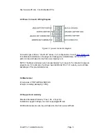
4.0 Power Connector Wiring Diagram 

Figure 1.3, power connector diagram 

Connector type is Molex “mini-fit JR” series, 2 x 4 configuration. Consult 

www.molex.com 

for additional information on housings and mating pins (male/female). All “mini-fit JR” 
parts can be purchased on-line from www.digi-key.com. 

NOTE: The Black and Green wire harness labeled “not connected” is intended to special 
projects use. For example, should you need additional 5V or 12V output, you could take 
advantage of this pre-installed wires. 

5.0 Mechanical 

-Dimensions: 210(W)x265(L)x66(H)mm 
-Weight, including packaging: 3.0Kg 

6.0 Support and warranty 

Standard Hardware Warranty 1Year / US, 2 Year EU 
Installation support: 30days via email, support@

cartft.com

Additional accessories can be purchased on-line from 

www.cartft.com

VoomPC-2  Installation Guide 

Page 6 
Summary of Contents for Automotive PC Enclosure VoomPC-2

Page 1: ...VoomPC 2 Automotive PC Enclosure Mini ITX Car PC Enclosure Installation Guide Version 1 0 P N VOOM PC 2 ENC Before you start ...

Page 2: ...times rushing into unit installation can result in serious damage to your motherboard power supply and probably your car s electrical system The VoomPC 2 has a wire harness that needs to be connected to the car s electrical system During installation always double check the polarity using a voltmeter VoomPC 2 Installation Guide Page 2 ...

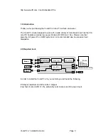
Page 3: ...MD systems is not recommended due to excessive heat dissipation 2 0 Required tools i ic PC SW i i GND Sw tch Log 6 30V ATX PSU ATX power MotherBoard ON OFF switch M1 ATX Battery Ignition J6 LED J4 J2 8b t MCU Amplifier Enable J8 Reverse and forward protect on Optional On OFF switch In order to install the VoomPC 2 in your vehicle you will need the following Phillips screwdriver and Wire cutter str...

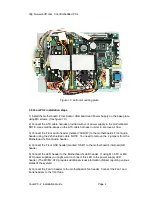
Page 4: ...motherboard s Front Audio header using the 2x5 shielded cable NOTE You need to remove the 2 jumpers from the Motherboard s Front Audio header 4 Connect the Front USB header marked USB to the motherboard s internal USB header 5 Connect the LED header to the Motherboard s LED header If using M1 ATX or M2 ATX power supplies you might want to connect this LED to the power supply LED header The M1 M2 A...

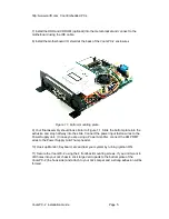
Page 5: ...op half way into the slide Connect the power input faston wires to the Power Supply unit In case you are using a Power Amplifier connect the AMP RMT wires to the Power Supply Anti Thump header 10 Hook up Monitor Keyboard etc and test your system by turning ignition ON 11 Secure the VoomPC 2 using the 4 front back mounting screws If you don t want to drill holes into your car chassis stick large Ve...

Page 6: ...ey com NOTE The Black and Green wire harness labeled not connected is intended to special projects use For example should you need additional 5V or 12V output you could take advantage of this pre installed wires 5 0 Mechanical Dimensions 210 W x265 L x66 H mm Weight including packaging 3 0Kg 6 0 Support and warranty Standard Hardware Warranty 1Year US 2 Year EU Installation support 30days via emai...

Reviews: