12/2008 - Art. Nr. 4200 1013 9300A
36
Maintenance
Maintenance works
Important
The burner should be serviced at least
once a year by a qualified specialist.
• Turn off the power supply at the all
pole switch.
• Check the absence of voltage.
• Close the fuel valve.
The setting values are indicated in the
paragraph entitled
“start-up”
Use only original parts.
• Remove the burner housing.
Cleaning
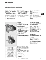
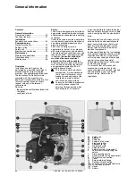
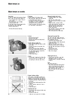
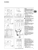
Shared access to the base plate
• Loosen the four plate mounting screws
on the housing by five turns.
• Dislodge the base plate and pull it
towards you until it is completely
released from the nozzle line.
• Hook the plate on the housing; there
are two options (see photos).
Dismantling the blast-tube
• Disconnect the power supply
connector.
• Unscrew the clamp screw.
• Remove the burner and place it on the
ground.
• Loosen the four screws for the
connecting nozzle by two turns and
remove the connecting nozzle.
• Replace, index and secure the
connecting nozzle.
• Reassemble all parts in the reverse
sequence to disassembly.
• Check the position of the hoses.
Cleaning the pump filter
The filter is located inside the pump
housing. It must be cleaned as part of
any maintenance work.
• Close the fuel oil intake valve.
• Place a container under the pump to
collect the fuel oil.
• Remove the screws and cover.
• Pull out the filter, clean or replace.
• Refit the filter and the cover using a
new seal.
• Screw down firmly.
• Open the fuel valve.
• Check it is airtight.
Cleaning the cover
• Clean the cover with a water and
detergent mixture. Do not use
chlorine-based or abrasive cleaning
products.
Note:
After each operation:
• Check the combustion parameters
under actual operating conditions
(doors closed, cover in place etc.),
and test the various circuits.
• Record the results in the relevant
documents.
Air box
• Remove the screw
K
.
• Remove the air box
• Remove any dust with a
dry
brush.
• Reassemble.
Combustion components
• Disconnect the ignition cables on the
electrodes.
• Remove and clean, or replace the
electrodes.
• Remove and clean the turbulator.
• Remove and replace the nozzle, using
the two wrenches (one to hold the
nozzle holder steady).
• Reassemble.
• Check the settings.
Volute
• Use a brush to remove dust from the
inside of the volute, the blower, the
connecting nozzle and the air flap.
Blower turbine setting
If the motor or the blower turbine are
replaced, the dimension
0
between
A
and
B
must be respected (see diagram).
• Tighten the turbine. Check that there is
no friction.
• Refit the base plate assembly on the
housing.
• Tighten the four screws in a cross
formation.
• Check the joints.
Cleaning the cell
• Remove the cell and wipe it with a dry,
clean cloth.
• Reassemble the cell.
Summary of Contents for NC4
Page 52: ...12 2008 Art Nr 4200 1013 9300A 52 R 1 2 9 BP1 BP1 B 2 BP2 R A4...
Page 54: ...12 2008 Art Nr 4200 1013 9300A 54 K 0 A B...
Page 55: ...12 2008 Art Nr 4200 1013 9300A 55 BP1 c 400...
Page 57: ...12 2008 Art Nr 4200 1013 9300A 57...
Page 58: ...12 2008 Art Nr 4200 1013 9300A 58...


