

1.
:
Switch the
power on
or standby.
2. : Press the button to display input source menu or
exit the menu screen.
3. : Press the button to return to previous menu
.
4
.
: Press the button to display desktop (Home page)
on the screen
.
5
.
: Press the button to open the setting menu
.
6. : Press the button to volume down
.
7. : Press the button to volume up
.
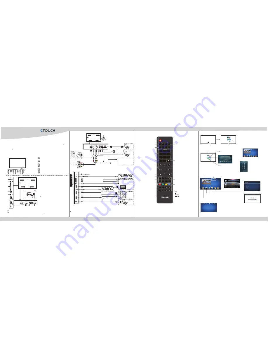
CTOUCH interactive display
Remote Sensor
Power Indicator
Identification of Controls
Note:
If the
does not receive a displaying signal for a certain time, the
goes into
standby mode.
CTOUCH interactive display
CTOUCH
Plug the power cord into an AC power outlet. Press
Power Switch
on the
.
CTOUCH interactive display
Now the
is in standby mode.
Wait a moment
until the power indicator lights up, then press
POWER
to turn
on the
. (Be sure to wait for a few seconds before pressing POWER button. If you promptly
press POWER button then the
may not respond or act wrongly.)
CTOUCH
CTOUCH interactive display
CTOUCH interactive display
Press button again to turn off the
and put the
in standby mode.
CTOUCH
display
To cut off the power completely, press
Power Switch
on the
.
back of the CTOUCH
Turning the CTOUCH interactive display on or off
AV devices
Y
W
R
Digital sound system
PC, etc.
VGA devices
Y
W
R
Serial port cable
VGA cable
AV cable
A
V
a
d
a
p
te
r
Network cable
Computer, etc.
Internet devices
Network connection
Before
using
headphones
,
adjust
the
device
volume so
as to avoid excessive levels, as
hearing damage may result.
S
/P
D
IF
c
a
b
le
Audio cable
Computer, etc.
Network cable
Headphone cable
Audio input devices
1. Connect the female plug to the AC socket on the unit.
2. Connect the male plug to the wall outlet as illustrated.
=
This product should be operated only from the type
of power source indicated on the marking label.
=
Always unplug the AC cord from power outlet when
not using for a long period of time.
Notes:
Tighten the W-iFi antenna in clockwise direction. The Wi-Fi
Inside AP. When network cable is plugged in WAN port, the antenna will generate Wi-Fi network.
antenna is able to access Wi-Fi network.
HDMI cable
USB cable
USB devices
3.0
2.0
HDMI cable
HDMI cable
P
C
O
U
T
VGA cable
Audio
cable
USB cable
USB devices
VGA cable
VGA cable
Audio
cable
HDMI devices
PC, etc.
VGA devices
Monitor
USB cable
Computer
U
S
B
Connect PC with VGA cable or HDMI cable.
Connect TOUCH OUT with USB cable to PC USB port.
Please choose the proper method of connection based on your device.
After
installation of the driver, it can control the external computer by native touch control.
(Only for
PC 1/2/3
、
HDMI 1/2/3 signal)
3.HDMI1/2/3 Input
To connect with those equipments with HDMI or DVI interface.
(A HDMI-to-DVI adapter cable is required when you are
connecting a DVI-equipped device to the
.)
4.VGA OUT
5.PC IN1/2/3
Enable connection to PC or other external devices with
VGA/AUDIO ports.
6.TOUCH OUT
7.AV IN
8.S/PDIF digital audio output
Connect a digital sound system to this jack.
9.
Connect headphones to this jack. The
is the current audio output.
10.LAN OUT
The built-in router output port. Connection to another computer
or other Internet enabled devices.
11.WAN IN
The built-in router input port. Connect to the external network.
12.RS232
For service, software upgrades and the other uses.
13. AC IN
Plug the AC cord into this jack and into a power outlet.(~100-
240V 50Hz/60Hz
)
14. Fuse: T6.3A 250V
15. Power Switch
Push to ( ) to connect the power, push to ( O ) to cut off.
Note
:
Power switch can not be covered, and should keep the
power switch can be conveniently operated.
CTOUCH
interactive display
CTOUCH interactive
display
Output the currently selected PC IN 1/2/3 signal.
Output the touch for external devices connected to PCx or
HDMIx port which support touch system.
Input port for composite video.
1. : Wi-Fi antenna .
2. USB2.0/3.0
USB
standard
interface
,
enable
connection
to
USB2.0, USB3.0
standard
devices
.
1
2
3
4
5
6
7
1
2
3
Quick Start Guide
CTOUCH Laser air
2
1
3
4
5
6
2
USB 3.0
USB
HDMI 1
HDMI 2
HDMI 3
VGA
OUT
P
C
IN
1
P
C
IN
2
TOUCH
OUT
VGA 2
VGA 1
AUDIO
AUDIO
5
7 8 9 10 11
12
AUDIO
AC IN
T6.3A 250V
13
14 15
Remote Control
0
1
2
3
4
5
6
7
8
9
0
1
2
3
4
5
6
7
8
9
USB
DVD
POWER
TV
INFO
MENU
PC
CH
VOL
P.M
OK
AV
VGA
RC-J55-0C
ZO OM
EXIT
SLEEP
MUTE
HOME
INPUT
S.M
HDMI
SNAP FREEZE
●
●
This operation manual provides a description based on operating functions with the remote control.
In different mode, some buttons may have different function.
Notes:
Select sound mode
Set up the sleep timer
Select picture mode
Select aspect ratio
Return to previous menu
or exit the on-screen menu
Mute the sound
Display or exit the setting menu screen
Coloured
buttons(RED/GREEN/YELLOW/BLUE)
delete or add a shortcut.
In all applications, use the red button to
Switch to HDMI mode
Switch to VGA mode
0-9 number buttons
Switch to AV mode
Switch to TV mode
Displ ay the
on the screen
int ernal PC mod ul e
Press to enter or exit the disc tray.
: Play/Pause button
: STOP button
/
: Fast forward/fast reverse
/
: Previous/next
Return to the previous channel
VOLUME UP/DOWN
Control buttons for USB Multi Media Player
Go to USB multi media player
Go to DVD multi media player
To confirm or enter a sub-menu or
toggle between options during MENU
operation.
Use Arrow buttons to navigate in on-
screen menu.
CHANNEL UP/DOWN
To freeze the current picture
Note:
If no DVD, this button has no function.
Note:
If no
, this
button has no function.
internal PC module
Note:
If no RF, this button has no function.
Switch the CTOUCH interactive display
power on or Standby
Display or exit input source menu
Display or exit the current
program information
Display desktop (Home page)on the screen
Take screenshot and store the
data onto
take screenshot
and store the data onto
or
USB Drive
.
your connected USB
storage device.
If USB storage device is not
connected ,
built-in
SDcard.
Folder's Location
:
go to
Applications
, then choose
ES
File Explorer
Note:
If no RF, this button has no function.
Connections
AUDIO
AC IN
P
C
O
U
T
A
V
O
U
T
V
ID
E
O
A
U
D
IO
Y
W
R
Notes
: 1.The
is multiple USB port designed(3.0, 2.0), when connect with USB device, please
select the appropriate port.
2.The VGA output is signal of what has been currently selected from PC1/2/3.
CTOUCH interactive display
USB 3.0
USB
HDMI 1
HDMI 2
HDMI 3
VGA
OUT
P
C
IN
1
P
C
IN
2
TOUCH
OUT
VGA 2
VGA 1
AUDIO
AUDIO
Basic Operations
1
2
3
Press and drag the MENU to any place of the
screen. Touch once to control the
surrounding MENU appear or disappear.
Touch once outside the MENU, the MENU
disappear.
When displaying at USB interface, touch
once at the lower part of the screen, the
display control menu will appear.
Touch the bottom of the
screen and drag upward
to make the MENU
appear.
1
2
3
Switch to the Home page (Android Interface)
Switch to different input source, i.e.
HDMI, VGA, etc.
Switch to the
menu screen
display
Switch to the
interface
internal PC module
Note:
If no
,
internal PC module this icon is not displayed
on
.
the screen
Display system program
Shortcuts
you created on Home page
Show
all applications
Go to your
web Browser
.
Open the
System Setup
menu.
Exit Android and go to display mode.
Go to your
USB multi-media player
.
Switch to the
interface
internal PC module
Home Page Overview
Note
: The layout of menu may vary upon different models you purchased.
A digital PDF manual to zoom in for better viewing can be found at:
www.ctouch.eu
.
Note:
If no
, VGA1 mode will be displayed on
the screen.
internal PC module
Touch the screen and drag to the left
direction to return to Home Page
Note:
When using the app Camera, store the data onto your connected USB
device. If USB device is not connected ,
built-in SDcard.
Folder's Location
:
go to
Applications
, then choose
ES File Explorer
store the data onto
or
USB Drive
.
Smart
innovation
!