background image

HV DTemp Measurement System – Using a HV DTemp Measurement System

User Guide

29

Version 01.00 // 2021

5.2  Configuration software DTEMPconfig

NOTE!

i

A configuration document (DBC file) is included in the scope of delivery 

of a HV DTemp measuring system. If the configuration document has to 

be changed, the configuration software DTEMPconfig is required. This 

software is available at CSM for a license fee. For further details please 

contact the sales department.. 

5 2 1  DTEMPconfig user interface

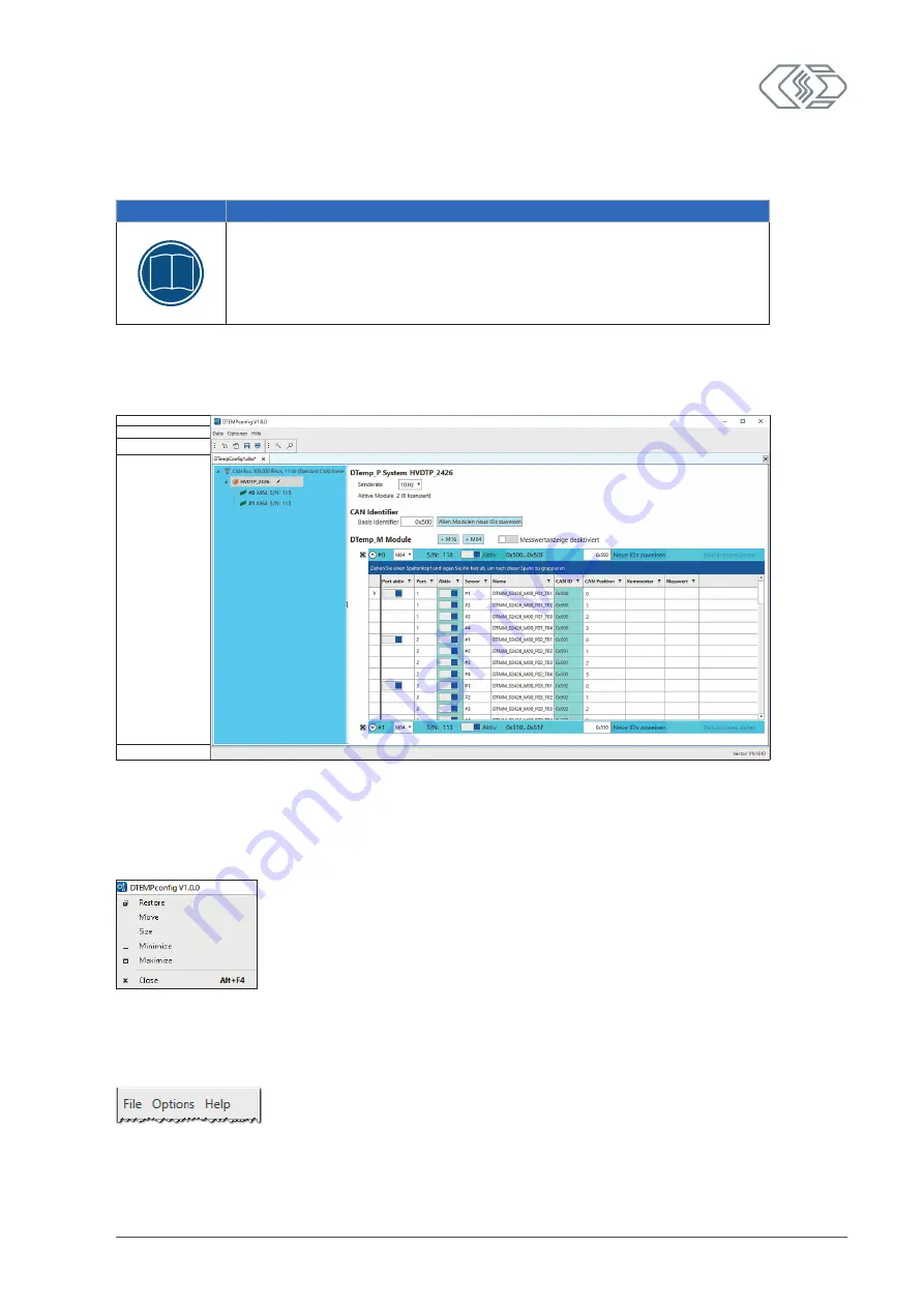
The DTEMPconfig software is used for the configuration of HV DTemp measurement systems.  

The DTEMPconfig user interface consists of the following sections:

Header

Menu bar

Toolbar

Working space with 

layout window

Status bar

Fig. 5-2:  DTEMPconfig user interface

Header

Clicking the program icon on the left opens the program menu. The program menu provides 

the usual functions for modifying the position and resizing of the program window. 

Fig. 5-3:  Program menu

Menu bar

The commands are arranged in the following menus:

Fig. 5-4:  Menu bar


→ See DTEMPconfig online help for further information on the menu commands.

Summary of Contents for HV DTemp Series

Page 1: ...Innovative Measurement and Data Technology HV DTemp Measurement System User Guide Version 01 00 ...

Page 2: ...quences Become familiar with local regulations for separate collection of electrical and electronic equipment Follow local regulations and do not dispose of old equipment with household waste Contact information CSM offers support for its products over the entire product life cycle Updates for the individual components e g documentation configuration software and firmware are made available on the...

Page 3: ...uctions 8 2 1 General Safety Instructions 8 2 2 Obligations of the operator 9 2 3 Intended use 10 3 Product Description 11 3 1 Connections and components 12 3 1 1 HV DTemp P central unit 12 3 1 2 HV DTemp M controller 13 3 1 3 Sensors and sensor assemblies 14 3 2 Functional description of LED indicators 15 3 2 1 CAN bus LED indicator 15 3 2 2 Measurement input LED indicators 15 3 2 3 Status LED in...

Page 4: ...7 4 3 3 7 Terminating a controller 27 5 Using a HV DTemp Measurement System 28 5 1 Typical example of a measurement application 28 5 2 Configuration software DTEMPconfig 29 5 2 1 DTEMPconfig user interface 29 5 3 Setting the central unit and the controller 31 5 3 1 Creating an offline configuration 31 5 3 2 Creating an online configuration 34 5 3 2 1 Starting the program 34 5 3 2 2 Creating a conf...

Page 5: ...am refers to important notes or additional information on a specific topic Options Interface Menu selection Menu items options and but tons are highlighted in bold The vertical bar separates the menu from the menu command The example on the right means Click on the Options menu and select the Interface option Select Options Interface Options Interface A menu selection integrated in the text The CA...

Page 6: ...hazard f Possible consequences of non compliance f Measures to avert the hazard Warning symbols used Symbol Meaning Hot surface This symbol indicates a possible risk of burns from hot surfaces Tab 1 2 Warnings Signal words In this user guide warnings containing the following signal words are applied Signal word Meaning CAUTION indicates a potential hazard Failure to follow this warning may result ...

Page 7: ...e safety gloves Disconnect the measurement module before starting work Tab 1 4 Symbols for directives 1 5 Liability disclaimer This guide and other documents are part of the product and contain important information for its safe and efficient use To maintain the high quality level the product is continuously being developed which may result in the product s technical details changing at short noti...

Page 8: ...duct is modified by the end user f the user does not observe the safety instructions and the product documentation f the product is operated with accessories or parts which are not explicitly approved for operation by the manufacturer of the product See chapter 2 Safety Instructions 1 7 ESD information The manufacturer of the product declares that HV DTemp Measurement System modules comply with th...

Page 9: ... for use of the CANopen family of profiles over EtherCAT DAQ Data AcQuisition e g DAQ software STG STrain Gauge DTemp Digital Temperature measurement HV DTemp measurement system for Digital Temperature measurements in HV environments EMC ElectroMagnetic Compatibility ESD ElectroStatic Discharge ECAT EtherCAT an Ethernet based field bus system developed by Beck hoff company and the EtherCAT Technol...

Page 10: ...sings Abbreviations Measurement module type AD Measurement module for measuring analog voltages CNT CouNTer measurement module BM Measurement module for the acquisition of current and voltage on live high voltage cables Breakout Module HV DTemp Measurement module for High Voltage Digital Temperature measurements OUT Signal output module for the generation of analog quantities PC CAN based Power Co...

Page 11: ...Series High voltage ECAT measurement modules in MiniModule housings for measuring analog voltages f HV AD CAN TBM Series High voltage CAN measurement modules in 19 inch test bench housings for measuring analog voltages Examples for the designation of older measurement modules f ECAT STGMM 6 ECAT measurement module for measurements with strain gauges with six measurement channels in a MiniModule ho...

Page 12: ...life threatening electrical shocks Make sure that work is only carried out by qualified and trained electricians DIN VDE 1000 10 Observe safety instructions WARNING HV DTemp P central units are applied in high voltage applications Improper use can be life threatening due to high voltage Make sure that this work is only carried out by qualified and trained personnel Observe safety instructions WARN...

Page 13: ...the device in operation again Make sure that a high voltage isolation test according to EN 61010 1 2010 is carried out at least every 12 months If there is reason to assume that the isolation barrier is defective a HV isolation test needs to be carried out immediately NOTE i Differences in potential between the module shield of the interface cable and the mounting location can falsify measurement ...

Page 14: ...ions stated in the technical specifications See HV DTemp datasheet for further information f Operational safety can only be ensured if the module is used in accordance with its intended use f Compliance with the intended use also means that this user guide must be carefully read and the instructions contained must be observed f Inspection and repair work must only be carried out by CSM f The opera...

Page 15: ...system from CSM has been developed for the precise digital and thus interference free recording of up to 512 temperature measurement points via a single cable connection to the HV DTemp P central unit A HV DTemp measurement system consists of a HV DTemp P central unit at least one HV DTemp M controller and the required sensors sensor assemblies or single sensors Fig 3 1 HV DTemp Measurement System...

Page 16: ... HV DTemp P central unit See chapter 3 1 2 HV DTemp M controller Communication between the HV DTemp P central unit and the configuration software or data acquisition system is performed via CAN bus Each measuring point is assigned its own CAN ID and this is documented in a DBC description file The temperature sensors can thus be uniquely assigned and identified Data transmission on the CAN bus is ...

Page 17: ...M64 The 4 pin sockets are used to f connect the controller to the central unit HV DTemp P using a high voltage safe cable or f daisy chain the controller to a further controller using a connection cable It is possible to connect up to eight 2 HV DTemp Mx controllers to one HV DTemp P central unit depending on the license and thus the maximum number of measuring points Fig 3 3 HV DTemp M controller...

Page 18: ...2021 3 1 3 Sensors and sensor assemblies Sensors are available for HV DTemp measurement systems as single sensors or as sensor assemblies Fig 3 4 Single sensors sensor assemblies for HV DTemp M controllers i Please contact our sales department for further details about sensors ...

Page 19: ...EDs provide information on the status of the corresponding measurement input LED Status Meaning off No controller with this ID detected and no channels configured for this ID 50 green flashing Measurement channel in configuration software selected 100 red continuously lit There is an ID conflict Check the encoding switch settings and restart the system 50 red 50 green flashing ID detected measurem...

Page 20: ... is required to regulate pressure and humidity Do not block the ventilation opening for the GORE membrane during installation or use NOTE i Trouble free operation and electrical safety can only be ensured if the module is correctly installed Ensure correct installation Operate the module only within the specified operating environment See HV DTemp datasheet for further information 4 2 Mounting an ...

Page 21: ...he mounting position must offer sufficient space to connect and disconnect the cables without kinking or clamping them f Avoid a mounting position in which the modules are subjected to continuous strong vibrations and or shocks Required parts materials f Four screws and a suitable screwdriver or wrench Mounting the module Fasten the module to the mounting position See CAN accessories datasheet for...

Page 22: ...eatening electrical shocks Opening the housing can be life threatening due to high voltage Never open the housing Do not carry out any mechanical or electrical modifications on HV measurement systems WARNING Connecting CAN bus measurement modules to an existing CAN bus system may affect the CAN bus behavior Improper handling of a CAN bus system may endanger life or cause damage to property Always ...

Page 23: ...Make sure that this work is only carried out by qualified and trained personnel The controllers and the sensors connected to them are connected to the HV DTemp P central unit using the 8 pin multi connector sockets Fig 3 2 If required the HV DTemp P central unit can be connected to ground using the M6 threaded hole in the top side of the front bracket Fig 3 2 4 3 2 1 CAN sockets The CAN sockets ar...

Page 24: ...ousing to ground Required parts materials f suitable ground cable The cross section of the ground cable depends on the cross section of the measuring cable multi connector cable For multi connector cables with a total cross section of 2 5 mm2 DIN VDE 0100 540 recommends ground cables with cross sections as follows f insulated copper conductor min 2 5 mm2 f non insulated copper conductor min 4 0 mm...

Page 25: ...d power supply system this value may drop below the minimum value specified for a module for a short time a few milliseconds when star ting the engine When operating these modules always ensure that the voltage applied to the last measure ment module in a power supply chain does not drop below the minimum value of 6 V Cable lengths The resistance of a connection cable causes a voltage drop in the ...

Page 26: ...0 10 Observe safety instructions The only component of the HV DTemp measurement system located outside the HV environ ment is the HV safe central unit HV DTemp P Like the sensors the controllers are located in the HV battery and thus within the high voltage range Since the HV battery cannot be switched voltage free the safety instructions for the installa tion of controllers and sensors must be st...

Page 27: ...aken to protect the cables from chafing or sharp edges 4 3 3 3 Plugging and unplugging connectors The following instructions apply to all plug connections of an HV DTemp controller 4 Take hold of the notch between plug and socket and pull the plug Fig 4 2 Never pull the cable directly Make sure that the ambient temperature does not exceed 85 C during insertion and removal Insert the plug slowly ax...

Page 28: ...de strain relief if necessary Do not bend the sensor cable by 90 directly at the end of a solder lug NOTE i When choosing the measuring point also make sure that a sensor will not be exposed to mechanical strain after mounting Never expose sensors to mechanical strain Sensor designs Currently single sensors and flexible circuits are used Both types are available with only individual sensors and as...

Page 29: ...ake sure that it is always isolated from the measuring point the lower side of the sensor is resting flat on the measuring point the bending radius does not drop below 7 5 D 6 when installing the connection cables Fig 4 9 the connection cables are not bent sharply or placed over sharp edges see Fig 4 9 NOTE i When placing the flexible circuits make sure that the circuit is not bent sharply but car...

Page 30: ...also be fixed in order to minimize mechanical strain For this purpose the controllers are equipped with mounting lugs which are used to attach the controller to the intended mounting location using suitable fastening material e g cable ties Fig 4 10 Controller mounting lugs 4 3 3 5 Encoding switches Whether only one or more controllers are connected to a measurement input you have to make sure tha...

Page 31: ...oding switch position 4 3 3 6 Setting the controller ID Switch ID 1 2 3 4 9 On On On On 0 Off On On On 1 On Off On On 2 Off Off On On 3 On On Off On 4 Off On Off On 5 On Off Off On 6 Off Off Off On 7 Tab 4 4 Encoding switches controller ID 4 3 3 7 Terminating a controller The Termination switch see Fig 4 11 is used to terminate a controller Switch position On indicates that termination is enabled ...

Page 32: ... of the following components f 1 HV DTemp P central unit f 1 High voltage battery equipped with 3 HV DTemp M64 controllers and various sensors f 1 data acquisition system PC with DTEMPconfig configuration software f 1 interface cable with power supply connectors f 1 measurement cable central unit controller f 2 controller connection cables f 1 CAN termination plug f 1 CAN interface f 1 power suppl...

Page 33: ...epartment 5 2 1 DTEMPconfig user interface The DTEMPconfig software is used for the configuration of HV DTemp measurement systems The DTEMPconfig user interface consists of the following sections Header Menu bar Toolbar Working space with layout window Status bar Fig 5 2 DTEMPconfig user interface Header Clicking the program icon on the left opens the program menu The program menu provides the usu...

Page 34: ...or connected hardware Tab 5 1 Toolbar commands Working space The configuration data is summarized in a configuration document and stored as a DBC file CAN In DTEMPconfig the data of a configuration is processed in the working space of the program in a two pane configuration window Fig 5 5 DTEMPconfig configuration window See chapter 5 3 2 2 Creating a configuration section Setting options in the l...

Page 35: ...DTemp Measurement System Offline configuration f There is no connection between configuration software and the central unit s The configuration document is created offline which means without connection to the measurement chain f The configuration is transferred to the measurement chain via DTEMPconfig at a later time after an online connection to the measurement chain has been established 5 3 1 C...

Page 36: ...N An empty configuration window opens Fig 5 8 DTEMPconfig New configuration document Insert central unit Move the mouse pointer to the CAN bus entry and right click The context menu opens Fig 5 9 Context menu Add new device Select Add new device from the context menu The Device Properties dialog opens Fig 5 10 Device Properties dialog ...

Page 37: ...n the DTemp_M Modules section No modules yet is displayed there so far Fig 5 12 Inserting a controller Select M64 or M16 in the DTemp_M Modules section A table for a corresponding HV DTemp M controller is inserted Fig 5 13 Controller inserted into the configuration The fields for the ID and the serial number S N display 0 or as with the central unit a yellow warning symbol This symbol indicates th...

Page 38: ... a suitable CAN interface f the latest version of DTEMPconfig is installed on the computer 5 3 2 1 Starting the program Start DTEMPconfig The program window opens the previously loaded configuration may be displayed If DTEMPconfig is connected to a measurement application via an interface and if this interface was already used in a previous session then it is usually displayed in the lower right h...

Page 39: ...conflicts However an automatic channel configuration in its actual sense e g setting the measurement range is not performed i To create an initial configuration with multiple new HV DTemp P central units CSM recommends using Auto Configuration because all new measu rement modules are set to the same CAN ID Reading in a configuration The configuration is read in using the Scan Bus command Start DTE...

Page 40: ...enerated auto matically It does not need to be created manually beforehand Fig 5 18 Creating a new configuration document Select File New Ctrl N An empty configuration document opens in the working space Fig 5 19 Empty configuration window Execute Scan Bus Ctrl B Fig 5 20 File Scan Bus The bus is checked for connected hardware The detected components are displayed in the left section highlighted i...

Page 41: ...ted components are listed on the left below the CAN bus level Fig 5 21 Information on how to save a configuration can be found in chapter Saving the configuration Setting options in the left section of the configuration window highlighted in blue f CAN bus level Right clicking opens the context menu The Edit command opens the CAN Bus dialog See chapter 5 3 2 3 Setting CAN parameters f Module level...

Page 42: ... right of these buttons to fade the measured temperature values in or out 10 equivalent to Toggle On Offline in CSMconfig f Measurement collection deactivated measurement values are not displayed f Measurement collection activated measurement values are displayed By default no measurement values are displayed i e the switch is in position Measurement collection deactivated Set the switch to Measur...

Page 43: ...3 Setting CAN parameters i If a new configuration was created via Auto Configuration or Scan bus then the CAN settings usually do not have to be changed manually Changing the CAN parameters may be necessary for example if f additional modules with higher measurement data rates are used in a measurement application f a data acquisition software is used that requires different CAN parameters Opening...

Page 44: ...the right shows the maximum bus load specified in the Settings dialog CAN defaults Busload limit The CAN bus load depends on the following parameters f Number of active controllers f Message type 29 bit messages require more bits per message than 11 bit messages which results in a higher bus load f Bitrate lower bitrate higher bus load Tab 5 2 CAN Bus dialog setting options Make the required setti...

Page 45: ... of the device type and the serial number Alternatively an individual user defined name can be entered f The name must contain at least 1 character and a maximum of 24 characters f Allowed characters are letters A Z a z digits 0 9 and underscore _ f The name has to begin with a letter or digit not an underscore Tab 5 3 Device Properties dialog setting options If Scan Bus or Auto Configuration are ...

Page 46: ...ffline and online configurations Right click on the device entry The context menu opens Fig 5 31 Context menu module level Write settings to device Select Write settings to device The following message is displayed Fig 5 32 Safety prompt before overwriting the old configuration Click OK to write the configuration to the device A message indicates the successful reconfiguration of the central unit ...

Page 47: ...ving operations using Save the existing configuration file is overwritten If a configuration file is to be saved under a different name or in a different folder the Save as menu command must be used Select a directory enter the desired name in the File name field and confirm with Save The configuration file with the file extension dbc is saved in the current folder The name of the newly created co...

Page 48: ... Fig 5 35 CSMconfig File Import foreign CAN DB Select File Import foreign CAN DB The Open dialog opens Pick the DBC file and confirm the selection by clicking Open The DBC file containing the HV DTemp configuration is imported and displayed in the configuration document here in the Tree View window Fig 5 36 Imported DBC file in CSMconfig 5 3 4 Changing the default settings The Settings dialog cont...

Page 49: ... enabled an individual CAN ID is assigned to every temperature measurement value Assign inactive channels If this option is enabled CAN IDs will also be assigned to inactive channels Device Scan Create additional module configurations If this option is enabled then additional module configurations which were detected at the bus but which are not included in the read out device configuration will b...

Page 50: ...el sockets LEMO Redel 2P 8 pin f L0B 5p CAN power supply sockets LEMO 0B 5 pin f CAN Bus system ART1550100 Part number of the measurement module Power 6 30 V DC typ 950 mW Power supply range typical power consumption Temp 40 C 125 C Operating temperature range S N 1 HVDTP Measurement module serial number Rating IP65 Protection class Revision A000 Hardware revision number Tab 6 1 Type label HV DTem...

Page 51: ...sulation test functional testing included f Repair service NOTE i An insulation test every 12 months is required in order to ensure the measurement module s operational safety Make sure that a high voltage insulation test according to EN 61010 1 2010 is carried out at least every 12 months 6 3 Cleaning instructions WARNING An HV DTemp P central unit is applied in high voltage applications Improper...

Page 52: ...aning User Guide 48 Version 01 00 2021 Requirements f All cable connections have been removed Required parts materials f Soft cloth f Mild detergent if necessary Cleaning the module Clean the module with a damp cloth Use mild detergent if necessary ...

Page 53: ... kink the sensor cable left but carefully bend it over the edge right 26 Fig 4 10 Controller mounting lugs 26 Fig 4 11 Encoding switches top side of controller 27 Fig 5 1 Measurement application with HV DTemp measurement system 28 Fig 5 2 DTEMPconfig user interface 29 Fig 5 3 Program menu 29 Fig 5 4 Menu bar 29 Fig 5 5 DTEMPconfig configuration window 30 Fig 5 6 The DTEMPconfig program window 31 F...

Page 54: ...l Write settings to device 42 Fig 5 32 Safety prompt before overwriting the old configuration 42 Fig 5 33 Save As dialog 43 Fig 5 34 New file name DTempConfig1 dbc 43 Fig 5 35 CSMconfig File Import foreign CAN DB 44 Fig 5 36 Imported DBC file in CSMconfig 44 Fig 5 37 Settings dialog 44 7 2 List of tables Tab 1 1 Symbols and writing conventions 1 Tab 1 2 Warnings 2 Tab 1 3 Signal words 2 Tab 1 4 Sy...

Page 55: ... Appendix User Guide 51 Version 01 00 2021 Tab 5 1 Toolbar commands 30 Tab 5 2 CAN Bus dialog setting options 40 Tab 5 3 Device Properties dialog setting options 41 Tab 5 4 Settings dialog setting options 45 Tab 6 1 Type label 46 ...

Page 56: ...ners Specifications are subject to change without notice CANopen and CiA are registered community trade marks of CAN in Automation e V EtherCAT is registered trademark and patented technology licensed by Beckhoff Automation GmbH Germany Our company is certified ...

Reviews: