Rugged, Reliable, Mobile, Secure
TM
1-800-260-9800
www.CRU-DataPort.com
eSATA/USB/FW800 to SATA DX115-DC HotDock Installation Guide
Mounting A Hard Drive In The Carrier
1. The metal cover for the HotDock carrier is secured by 2 screws.
Remove the screws and slide the top cover off the carrier.
2. Slide the hard drive in from the front of the carrier into the SATA
connector on the carrier circuit board. Secure the hard drive from the bottom
with the provided screws and replace the top cover.
NOTE: the HotDock does not support SAS drives
Operation
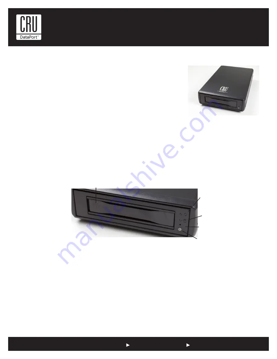
Power On Switch and Power Button
The DX115-DC SATA HotDock has both a power switch on the back and a power button on the front. When the power switch on the back is turned
on, the unit will power up automatically when a carrier is inserted. The power button on the front can be used to turn off a powered up unit. The
unit can be repowered by pushing the power button (or by removing and reinserting the carrier).
Drive Ready/Error LED
This bi-color LED indicates either the status of the drive or fan/DC power, depending on the color.
Drive Ready (blue)
: Flashing blue LED indicates that drive is inserted and powering up. Steady blue LED glow indicates drive is powered on and
ready for access.
Error (red):
Flashing red and blue LED indicates a fan failure. Steady red LED glow indicates DC power failure.
Drive Activity LED
This amber LED indicates when the host computer is accessing the data on the drive. LED will flash during communication with the host computer.
Fan Error LED Disable Button
This button allows the user to disable the Fan Error LED (insert a paper clip or similar object to disable). CRU-DataPort recommends replacing a faulty
fan immediately. Contact CRU-DataPort for spare fan ordering information.
Power
Button
Drive Ready/
Error LED
Drive Activity LED
Fan Error LED
Disable Button
Push Here to Eject Carrier
Figure 1: Front Bezel


