Rugged, Reliable, Mobile, Secure
TM
1-800-260-9800
www.CRU-DataPort.com
DE100 Ultra320 SCA
Removable SCSI Wide Ultra320 Drive Enclosure with 80-Pin SCA Interface
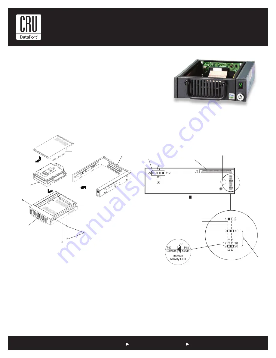
Drive Installation Assembly
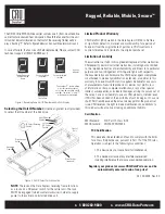
Receiving Frame Motherboard
Option Pin Connector (W1)
Remote Unit ID Selection:
Pins 1-8 of this connector are provided
for remote unit SCSI ID selection through the computer system.
Remote ID selection requires that the unit ID switch located on the
inside of the receiving frame be set to “0” (onboard ID selection is set
with a switch located on the inside of the receiving frame).
Remote Activity LED (RLED):
Pins 17 & 18 provide power for a
remote LED device activity indicator.
Factory-Installed Jumpers: There are two factory-installed jumpers on
W1. This jumpers are located on Pins 9 & 10 and 19 & 20.
NOTE: Do not remove these jumpers!
The Ultra320 DE100 drive carrier contains one (1) front-mounted drive car-
rier fan for enhanced heat dissipation. Should the fan ever fail, the unit ID
number indicator (located on the front of the receiving frame) will display a
flashing “F” (refer to figure below) and an audible alarm will sound.
In case of failure, the fan is easily field-replaceable. Refer to the full
version of the DE100 Ultra320 SCA User’s Guide for further information.
NOTES:
For SCSI Ultra320 operation, the DE100 Ultra320 SCA requires Ultra320
drives, Ultra320 HBA, and Ultra320-compliant cabling (internal and external).
DE100 Ultra320 SCA can support Ultra320 implementations with a maximum of fifteen
(15) Ultra320 drives (Ultra320 repeater may be required).
DE100 Ultra320 SCA receiving frames are indicated by their BLUE LED, while the
Ultra320 DE100 carriers are indicated by the Ultra320 logo.
Figure 1: Drive Installation Overview
Note:
Installation of drive cover is necessary for proper fan air flow!
Drive Cover
(provided)
Receiving Frame
Motherboard
Receiving
Frame
Drive Carrier
Board
#6-32-Phillips
F.H. Screw
(6 Total)
Drive
Carrier
Front-Mounted
Fan
Drive
(not included)
DC Power
Connector
(P1)
68-Pin I/O
Connector
(J3)
Buzzer
Option Pin
Connector
(W1)
Factory-Installed
Jumpers
(do not remove)
Remote ID Select
{
GND
ID0
ID1
ID2
ID3
= Pin 1
Figure 2: Receiving Frame Motherboard (rear view)


