Installation and Operating Instructions
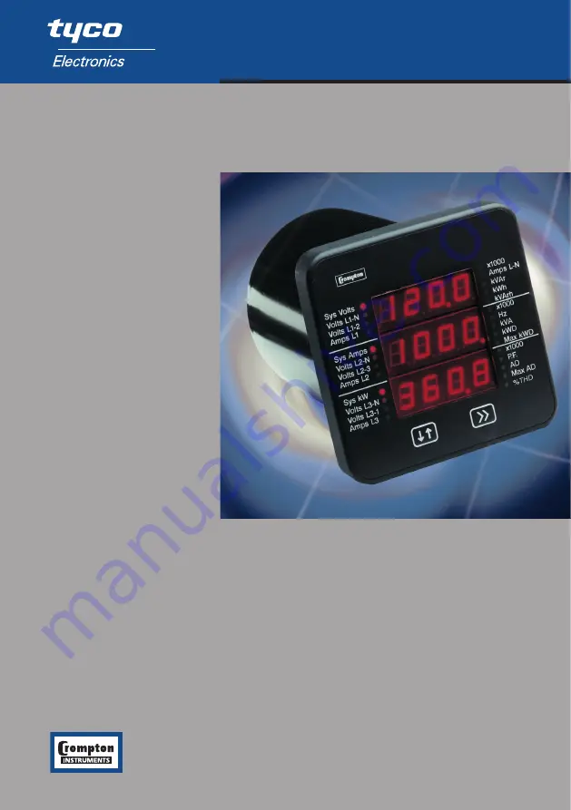
SWITCHBOARD INTEGRA 1540
http://energy.tycoelectronics.com
Energy Division
Tyco Electronics UK Limited
Crompton Instruments
Freebournes Road, Witham, Essex, CM8 3AH, UK
Tel: +44 1376 509 509
Fax: +44 1376 509 511


