background image

SmarTouch STS Touchpanels 

Crestron 

ST-1550 & ST-1550C


To configure the touchpanel, it may be necessary to access a series of setup screens 
prior to viewing run-time screens that are loaded into the touchpanel for normal 
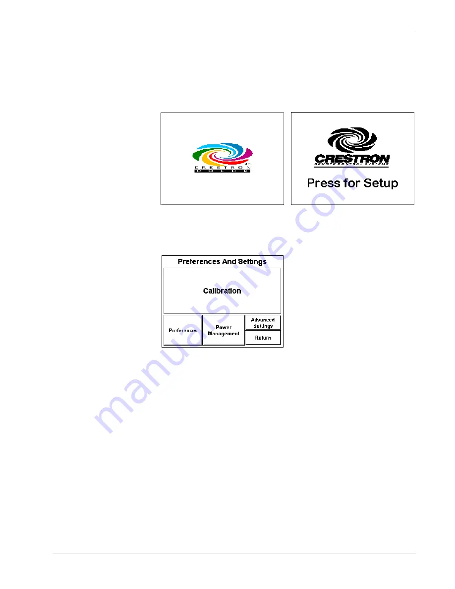
operation. The Opening Screen, shown below, appears when a finger is held to the 
touchscreen for approximately three seconds as power is applied. This screen 
indicates that you are in “setup mode” and can proceed to configure the touchpanel.  

Opening Screen for ST-1550C (left) and ST-1550 (right) 


Remove your finger and touch the Opening Screen again to display the Preferences 
and Settings Menu, shown after this paragraph. All resources to configure the 
touchpanel are available from this menu.  

Preferences and Settings Menu 


The Preferences and Settings Menu displays five buttons: 

Calibration

Preferences

Power Management

Advanced Settings

, and 

Return

. The 

Return 

button saves all 

of the setup information to EEPROM and displays the main page that has been 
programmed into your system.  

Calibration 

NOTE:

  Calibration works best  

when performed with a narrow,  
blunt instrument (i.e., pencil eraser).  

Calibration of the touchscreen is required if the active touch area of a button does 
not coincide with the button’s image. Select the 

Calibration 

button to initiate 

“calibration mode”. The touchpanel prompts you with a message, “Touch Upper 
Left Corner”. Touch the corner of the screen; be as accurate as possible. Another 
message, “Touch Lower Right Corner”, appears. Perform the operation to complete 
calibration and return to the Opening Screen.  

If the 

Calibration 

button from the Preferences and Settings Menu cannot be reached, 

complete the following steps. 

1.  Remove power (ST-BTP, ST-DS, and/or external AC power pack). 

2.  Reapply power while holding a finger to the touchscreen for at least 

three seconds. During this short period, the words “SETUP MODE” 

4  

  SmarTouch STS 

User's Operations Guide - DOC. 5804 

Summary of Contents for SmarTouch STS ST-1550

Page 1: ......

Page 2: ......

Page 3: ...Cleaning 3 Applying Power 3 Configuring the Touchpanel 3 Calibration 4 Preferences Menu 5 Power Management 7 Advanced Settings 8 Internal Scheduler 9 Button Sequence Development 9 Scheduling a Sequen...

Page 4: ......

Page 5: ...TRANSMISSION FREQUENCY STS Grayscale 120V AC 433 92 MHz STS C Color 120V AC 433 92 MHz STSI Grayscale 220V AC 433 92 MHz STSI C Color 220V AC 433 92 MHz STSI UK Grayscale 220V AC 418 MHz STSI C UK Col...

Page 6: ...Views A battery compartment is located on the underside of the unit The compartment holds one Crestron ST BTP rechargeable power pack There are also four rubber feet on the underside of the unit for s...

Page 7: ...age quality For best cleaning results use a clean damp non abrasive cloth with any commercially available non ammonia glass cleaner Surrounding plastic enclosure may not provide a complete water tight...

Page 8: ...ettings and Return The Return button saves all of the setup information to EEPROM and displays the main page that has been programmed into your system Calibration NOTE Calibration works best when perf...

Page 9: ...NOTE Detach the external AC power pack when viewing Battery Life Screen If this pack is attached the gauges read full charge which may be misleading To obtain the Battery Life Screen shown after this...

Page 10: ...Up Minute Down Minute Up Second Down and Second Up to synchronize the time values in the scratchpad to the current time To save the settings in the scratchpad to the touchpanel s internal clock and re...

Page 11: ...rogrammed onto any page in the project Consult your dealer To reactivate the touchpanel after the Off or Standby buttons have been utilized simply press the touchscreen Contrast Screen contrast may ne...

Page 12: ...shown in the illustration Minutes can vary from 0 to 120 where 0 disables the timeout Down and up arrow buttons decrease and increase the timeout respectively NOTE Power Down Timeout should be set low...

Page 13: ...sonal layout details of your system Button Sequence Development A button sequence differs from macros created from the Control pull down menu of the programming software because the end user can assig...

Page 14: ...grammed sequence or one that initiates a specific function 3 To set the activation time for the event touch an Adjust Time button from the scratch schedule to open another page Use the increment decre...

Page 15: ...lable These configurations are identical except for display color the type of input power required and the transmission frequency The table shown in Functional Description on page 1 provides a breakdo...

Page 16: ...to be connected via the STIRP to each IR OUT port For example in the connection diagram provided the STIRP in IR PORT A is attached to the VCR 4 Repeat the previous step as necessary 5 Apply power to...

Page 17: ...plied to the system function LEDs on Touchpanel is incorrectly calibrated Enter setup mode and correct Refer to Interface Menu ST CP do not illuminate RF LED on ST CP does ST CP is not receiving power...

Page 18: ...SmarTouch STS Touchpanels Crestron ST 1550 ST 1550C This page intentionally left blank 14 SmarTouch STS User s Operations Guide DOC 5804...

Page 19: ...Crestron ST 1550 ST 1550C SmarTouch STS Touchpanels User s Operations Guide DOC 5804 SmarTouch STS 15 This page intentionally left blank...

Page 20: ......

Reviews: