background image

Touchpanel Media Centers   

Crestron Isys i/O


TPMC-15/17 Tilt Series


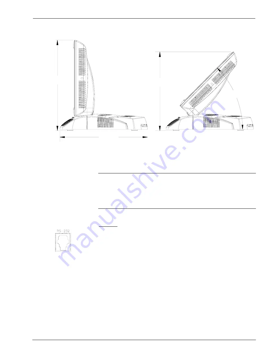
Physical Views of the TPMC-15 & TPMC-17 Touchpanel (Side with Min. and Max. Angle) 

13.74 in

(34.90 cm)

14.17 in

(35.99 cm)

12.40 in

(31.50 cm)

45°


Ports and Pushbuttons 

All connections to the TPMC-15 and TPMC-17 are made through the ports on the 
rear panel. Refer to the illustrations and descriptions that follow. 

NOTE:  

An integrated cover and cable strain relief hide connections to the 

touchpanel. For more information on the cover and strain relief, refer to “Cable 
Management” on
 page 48.


NOTE: 

 An interface connector for the NET port is provided with the TPMC-15 and 

TPMC-17. 

RS-232 


This 6-pin RJ-11 connector mates with a 9-pin serial port of a PC. The connecting 
cable is not supplied. Use this port to establish a direct connection between the 
touchpanel and a PC without a control system or network connection. Once the direct 
connection is established, touchpanel files and firmware updates can be uploaded to 
the touchpanel. Additionally, the touchpanel’s diagnostic tools can be accessed over 
the direct connection. In the event that modular cables or an RJ-11 to DB9F adapter 
is not available, the following table and diagram provide information so that the cable 
can be fabricated on site. Refer to “Touch Screen” on page 30 for RS-232 port 
configuration settings.


14  

  Touchpanel Media Centers:  Crestron Isys i/O™ TPMC-15/17 Tilt Series Operations 

Guide - DOC. 6344 

Summary of Contents for Isys i/O TPMC-15-CH

Page 1: ...Crestron Isys i O TPMC 15 17 Tilt Series Touchpanel Media Centers Operations Guide ...

Page 2: ...ectronics Inc 15 Volvo Drive Rockleigh NJ 07647 1 888 CRESTRON All brand names product names and trademarks are the property of their respective owners Windows and Windows XP are registered trademarks of Microsoft Corporation in the United States and other countries 2005 Crestron Electronics Inc ...

Page 3: ...g the Touchpanel 25 Cable Management 48 Hardware Hookup 48 Recommended Cleaning 49 Programming 49 Uploading and Upgrading 50 Establishing Communications 50 Troubleshooting Communications 59 Uploading a SIMPL Windows Program 60 Uploading a VT Pro e Project 61 Firmware Upgrade 64 Operation 66 MediaMarker 66 Security Infrastructure 66 Problem Solving 68 Troubleshooting 68 Further Inquiries 69 Future ...

Page 4: ......

Page 5: ...s of the TPMC 15 series Both the TPMC 17 and TPMC 15 are available in QuickMedia hereinafter referred to as QM and Crestron Home hereinafter referred to as CH versions TPMC 15 TPMC 17 Series Functional Summary Microsoft Windows XP Embedded operating system with integrated applications such as Internet Explorer Windows Media Player Netmeeting Remote Desktop and viewers for Word Excel PowerPoint and...

Page 6: ... multiple QM origination points when acting as an endpoint QM versions only Stores and transmits audio parameters for recall by a QM receiver when acting as a QM origination point QM versions only Two USB ports for connecting with USB peripherals One RS 232 port for project upload firmware upgrade and diagnostics Two PCMCIA card slots for further expansion including installation of wireless networ...

Page 7: ...ution integrating conventional AV control with embedded PC applications for browsing the Internet and presenting a full range of multimedia content Sound Video The TPMC 15 and TPMC 17 feature a built in biamplified speaker system and a headphone jack Sound can be generated by the touchpanel using downloaded wave files WAV a PC application or can be mixed in from an external line level audio source...

Page 8: ...Diagram QuickMedia While acting as a QM receiver QM versions of the TPMC 15 17 can be connected to any combination of QM switching devices and or QM transmitters to expand the number of available QM inputs as shown in the following diagrams TPMC 15 17 QM Connected with Other QM Switching Devices 4 Touchpanel Media Centers Crestron Isys i O TPMC 15 17 Tilt Series Operations Guide DOC 6344 ...

Page 9: ...MediaManager devices are designed for conference room auditorium and lecture hall applications or anywhere else where audio video or computer equipment needs to be easily connected and disconnected from a presentation system or room control system The following diagram shows a TPMC 17 QM in a lecture hall application TPMC 15 17 QM in Lectern Application The TPMC 15 CH and TPMC 17 CH are integral t...

Page 10: ...ilable on QM versions only MediaMarker can be used with the TPMC 15 TPMC 17 or a personal computer In addition to containing the tools required for object creation MediaMarker can import graphics and text from many other applications Importable objects include HTML JPG BMP PNG and TIF MediaMarker projects can be saved and retrieved to compact flash or a mapped network drive Refer to page 66 for ad...

Page 11: ...ork adapter Two built in USB ports can be used to connect to mass storage devices or other USB peripherals Program loading can be accomplished via any mass storage device or through Compact Flash A USB drive connected to one of the USB ports or a PCMCIA Flash Card adaptor card and flash memory card can be used for the Word Excel and other files that can be read by the embedded applications The fla...

Page 12: ... PAL Delay compensation up to 22ns on input labeled QM1 CH Version 2 Balanced analog RJ 45 video inputs over CAT5 from CNX PVID or similar device Supports YPRPB S video and composite NTSC or PAL Audio Inputs QM Version 2 QuickMedia channels over RJ 45 Each input carries one pair of stereo signals plus microphone audio CH Version 1 Balanced analog RJ 45 audio input over CAT5 Carries audio from CNX ...

Page 13: ...hone jack on rear of unit 105 mW per channel 8 ohm load CH Version Balanced line level microphone with AGC output via RJ 45 output to CNX BIPAD8 600 Ω impedance Maximum Microphone Output 2 Vrms Balanced 600 Ω line level stereo input through RJ 45 input Maximum input level 4 Vrms with internal volume control and mono biamplified 2 way speakers Built in WAV file 8 16 bit 8kHz to 44kHz sampling rate ...

Page 14: ...FT Active matrix color LCD TPMC 15 15 38 1 cm 4 3 aspect ratio TPMC 17 17 43 2 cm 15 9 aspect ratio TPMC 15 4 3 XGA TPMC 17 15 9 WXGA TPMC 15 1024 x 768 pixels TPMC 17 1280 x 768 pixels TPMC 15 400 nits TPMC 17 450 nits TPMC 15 300 1 TPMC 17 400 1 Back lit fluorescent TPMC 15 H 170 o V 170 o TPMC 17 H 176 o V 176 o Resistive membrane Graphic Engine 24 Bit non palette graphics 8 Bit alpha transpare...

Page 15: ... access to certain areas of the site including the FTP site Physical Description The touch sensitive viewing screen is located on the front of the touchpanel The TPMC 15 s 15 inch 38 1 cm screen has a 4 3 aspect ratio while the TPMC 17 s 17 inch 43 2 cm screen has a 15 9 widescreen aspect ratio The electronic hardware is housed in a black molded plastic enclosure with silver accent as shown in the...

Page 16: ...Touchpanel Media Centers Crestron Isys i O TPMC 15 17 Tilt Series TPMC 15 Front View TPMC 17 Front View 12 Touchpanel Media Centers Crestron Isys i O TPMC 15 17 Tilt Series Operations Guide DOC 6344 ...

Page 17: ...nector Cover 14 94 in 37 95 cm 14 17 in 35 99 cm 11 94 in 30 33 cm 11 30 in 28 70 cm Physical Views of the TPMC 17 Touchpanel Front and Back Shown without Rear Connector Cover 11 30 in 28 70 cm 11 94 in 30 33 cm 14 17 in 35 99 cm 17 63 in 44 77 cm Operations Guide DOC 6344 Touchpanel Media Centers Crestron Isys i O TPMC 15 17 Tilt Series 13 ...

Page 18: ...he TPMC 15 and TPMC 17 RS 232 This 6 pin RJ 11 connector mates with a 9 pin serial port of a PC The connecting cable is not supplied Use this port to establish a direct connection between the touchpanel and a PC without a control system or network connection Once the direct connection is established touchpanel files and firmware updates can be uploaded to the touchpanel Additionally the touchpanel...

Page 19: ... USB Two Universal Serial Bus USB A connectors provide a communications link to a variety of third party USB peripherals USB is a connectivity specification developed by the USB Implementers Forum that provides a single simple standardized way to connect up to 127 devices to a computer USB shielded cables contain two wires for power 5 volts red and ground brown and a twisted pair of wires yellow a...

Page 20: ...e equipment damage or void the Crestron warranty PHONE Connect this standard mini phone jack 105 mW per channel 8 ohm load to the plug of an external headphone set not supplied PC CARD Two Type II PCMCIA Card slots used for memory expansion up to 4GB or more VT Pro e project uploads or installation of a wireless network card A cover is secured over the slots to protect the electronics Use a 1 Phil...

Page 21: ...ce Y 2 ORANGE GREEN Composite Luminance Y 3 WHITE GREEN WHITE ORANGE N A Chrominance PB 4 BLUE BLUE N A N A PR 5 WHITE BLUE WHITE BLUE N A N A PR 6 GREEN ORANGE N A Chrominance PB 7 WHITE BROWN WHITE BROWN N A N A N A 8 BROWN BROWN N A N A N A 1 8 1 8 Front Top Audio In Out Pin Assignments PIN WIRE COLORS 568B WIRE COLORS 568A AUDIO I O 1 WHITE ORANGE WHITE GREEN Mic Left Out 2 ORANGE GREEN Mic Le...

Page 22: ...Input 2 is capable of the following QM Input 2 Maximum Cable Length SIGNAL TYPE RESOLUTION MAXIMUM CABLE LENGTH FEET Video S video 480i 300 Component 480p 300 Component 720p 300 Component 1080i 300 RGB 1024 x 768 75 Hz 69 RGB 1280 x 1024 75 Hz 40 RGB 1600 x 1200 60 Hz 20 RGB 640 x 480 60 Hz 216 RGB 800 x 600 60Hz 136 RGB 1024 x 768 60Hz 84 RGB 1280 x 768 60Hz 50 With CresCAT QM cable available fro...

Page 23: ...nvert unbalanced video sent over coax cable and balanced unbalanced audio sent over shielded twisted pair wiring to CAT5 cabling for connection to the TPMC 15 CH or TPMC 17 CH touchpanels NOTE When using a TPMC CH IMC to provide video and audio to the touchpanel any source that is to use the second input will only be able to send video to the touchpanel as the audio port will be connected to the a...

Page 24: ...S video component video RGBHV and audio signals These signals are encoded and converted to the QuickMedia standard and fed over a CAT5E or CAT6 cable to a QM receiver such as the TPMC 15 17 QM All signal routing occurs automatically under the command of the control system For more information refer to the latest version of the QuickMedia Transmitter QM TX Operations Guide Doc 6334 Tilt Angle Tensi...

Page 25: ...at interference will not occur in a particular installation If this equipment does cause harmful interference to radio or television reception which can be determined by turning the equipment off and on the user is encouraged to try to correct the interference by one or more of the following measures Reorient or relocate the receiving antenna Increase the separation between the equipment and recei...

Page 26: ...unit is a home run from a Crestron system power supply network port the Cresnet power usage of that unit is the Cresnet power usage of the entire run The length of the run in feet and the Cresnet power usage of the run should be used in the following resistance equation to calculate the value on the right side of the equation Resistance Equation R Resistance refer to the following table L Length o...

Page 27: ...mmended cable lengths for various signal formats Recommended Maximum Cable Lengths for Audio Video via CAT5 FORMAT MAXIMUM DISTANCE Composite 750 feet S Video 750 feet Component 500 feet Audio 1000 feet For more information refer to the latest version of the Crestron CAT5 Wiring Reference Guide Doc 6137 QM Network Wiring QM Versions Only For the QuickMedia transport use CRESCAT QM cable The aggreg...

Page 28: ...e of managing computer video and audio signals simultaneously through one CAT5E or CAT6 UTP unshielded twisted pair wire simplifying installations Routing CAT5E or CAT6 UTP cable is less expensive and much simpler than routing multi colored multi conductor coax cable All Crestron products using the QM transport system are capable of sending and receiving QM signals via standard CAT5E or CAT6 cable...

Page 29: ...esistance and capacitance of longer cable lengths and is not particular to either Crestron and or QuickMedia systems To ensure sufficient bandwidth to support signal resolutions up to 1600 x 1200 the maximum aggregate cable length should not exceed 328 feet The use of lower resolution signals may allow increased cable length but must be tested by the installer with the sources to be used For pin a...

Page 30: ...nsitive After logging in the password can be changed from the Security window Refer to page 28 for more information 4 When the TPMC Debug Output window appears shown below select Project Enter Setup Mode to enter the SETUP MENU shown on page 27 TPMC 15 QM Debug Output Window Via Crestron Toolbox NOTE The Crestron Toolbox replacement for Crestron Viewport you may continue to use Viewport if desired...

Page 31: ...on page 50 2 Right click on the device and select Functions Setup Mode Setup Calibrate Window 3 Select Enter Setup Mode The SETUP MENU will be displayed as shown in the following diagram NOTE Select Exit Setup Mode to exit the SETUP MENU TPMC 15 17 CH SETUP MENU Operations Guide DOC 6344 Touchpanel Media Centers Crestron Isys i O TPMC 15 17 Tilt Series 27 ...

Page 32: ...SETUP MENU SETUP MENU Details The SETUP MENU allows configuration of the touchpanel s settings for security Cresnet RS 232 communications display runtime project video audio annotation and embedded applications Security The Security button opens the Security Setup window which allows the user to change the username and password of the system account setup and close network connections and clear co...

Page 33: ...nnection 1 Map this connection by selecting a drive letter from the Map Drive Letter drop box 2 Enter a User Name and Password 3 Click the Remember and reconnect on startup checkbox if so desired 4 Click OK to enable the new network connection and return to the Network Connections window Once all changes to network connections have been completed click OK to return to the SETUP MENU Cresnet The Cr...

Page 34: ...C 17 is factory set to 03 No two devices in the same system can have the same Net ID Two buttons below the hexadecimal display UP and DOWN increase and decrease the CRESNET ID by one respectively Select OK to accept the changes and return to the SETUP MENU Touch Screen The Touch Screen button determines if the RS 232 serial port is used for communicating with other devices Enabled must be selected...

Page 35: ... in the correct corner Touch the center of the cross hair in the corner of the screen to conclude calibration and return to the Touch Screen Console Settings window NOTE When touching the screen during calibration be as accurate as possible Use the tip of a capped pen or the eraser end of a pencil To cancel calibration and return to the Touch Screen Console Settings window without saving calibrati...

Page 36: ...ect the network drive and or flash drive where the compiled project is located After selecting the location of the compiled project select Browse to find the compiled project file NOTE Selecting the External option permits you to connect to a network drive USB devices and the PC Card ports on the rear of the TPMC 15 or TPMC 17 NOTE If External is checked the display list cannot be viewed via Crest...

Page 37: ...ions only RGB is setup using the Size Position Color and Lock Sync controls The following test patterns are recommended for adjustment Lock Sync A vertical alternating black white lines line test pattern screen is recommended Lock Sync is available for RGB only NOTE The vertical line test pattern should look uniform If you see dark vertical bars in the test pattern adjust Coarse to eliminate bands...

Page 38: ...nt and back porch and sets them for the selected input Auto calibrate is a one time setting that is performed in the Video Setup window for each RGB input You must select the source and have it display before selecting Auto from the Calibrate area You can return to this setup screen when you want to perform auto calibrate in the future If this selection does not look correct select default calibra...

Page 39: ... of the scan lines To reliably eliminate the noise and fill the screen with a picture the outside edge of the active picture area was pushed out past the edge of the display area The average or targeted over scan loss is about 5 to 10 of the image on each edge Digital images have nearly eliminated the noise and other artifacts at the edge of the picture so more of the video image can be safely sho...

Page 40: ...ensate for the varying distances that a video signal must travel in a QM cable NOTE QM Input 2 on the TPMC 15 QM and the TPMC 17 QM does not have adjustments for skew compensation Up to 255 preset locations are available to store settings for peak boost and skew In QM systems using auto compensation the touchpanel can be set to automatically recall preset values upon receipt of a QM ID by selectin...

Page 41: ...or all versions of the TPMC 15 17 pressing Play Test plays a short internal audio file Volume and balance adjustments are available for the Local Audio Microphone Headphones and an overall Speaker volume and balance control In addition the key click sound can be enabled or disabled by pressing Key Click Defaults are 25 for volume and zero for balance Changes to audio settings are made in real time...

Page 42: ...wn in the following diagram It includes tabs containing controls for the QM inputs and the QM output Audio Setup Window QM Version From the QM Inputs tab volume levels for the program and microphone audio can be adjusted for each of the QM inputs 38 Touchpanel Media Centers Crestron Isys i O TPMC 15 17 Tilt Series Operations Guide DOC 6344 ...

Page 43: ...ollowing diagram Additionally the touchpanel can be set to transmit the touchpanels actual QM ID or a specific QM ID for use in QM systems using auto compensation For more information on auto compensation refer to the latest version of the Crestron Isys i O TPMC 15 TPMC 17 Series Programming Guide Doc 6350 Audio Setup Window QM Output Tab Operations Guide DOC 6344 Touchpanel Media Centers Crestron...

Page 44: ...the frame prefix followed by a sequential frame number The frame template serves as a starting point for each new frame Crestron supplies some ready made templates or you can use one of your own Screen captures can automatically save the contents of the current annotation frame to an image file The file will be saved as the default file type HTML JPG BMP PNG or TIF as specified in the session fold...

Page 45: ...iate for most internet sites Low Minimal safeguards and warning prompts are provided Most content is downloaded and run without prompts All active content can run Appropriate for sites you absolutely trust Press Default to restore the default security settings By default security is set to High for internet Medium for intranet and Low for trusted sites The Embedded Apps window also permits you to ...

Page 46: ...to appear that contains the text This operation has been cancelled due to restrictions in effect on this computer Please contact your system administrator If this message appears checking Enable Popup Windows in the Embedded Apps window may correct this error Other restrictions may also cause this error so this may not prevent all occurrences ETHERNET Details The ETHERNET MENU allows configuration...

Page 47: ...thernetExternal Properties window This window displays the connection and related required items EthernetExternal Properties Window To establish dynamic or static processing select Internet Protocol TCP IP and click Properties Operations Guide DOC 6344 Touchpanel Media Centers Crestron Isys i O TPMC 15 17 Tilt Series 43 ...

Page 48: ...me it connects to the network In some systems the IP address of the device can even change while it is still connected DHCP also supports a mix of static and dynamic IP addresses Dynamic addressing simplifies network administration because the software keeps track of IP addresses rather than requiring an administrator to manage the task New computers can be added to a network without manually assi...

Page 49: ...roup that identify the touchpanel on the network The hostname may be used when transferring a program over Ethernet using Crestron Toolbox This window permits editing of the hostname and workgroup Network ID Window NOTE The hostname is required for Ethernet communication Sharing Press Sharing to open the Configure Shared Folders window This window is used to set up shared folders Sharing enables r...

Page 50: ...essages Following are definitions of each message type Warning An event occurred that may affect the normal operation of the unit Error An operation has failed Fatal An event occurred which will require the unit to be reset The Diagnostics Window in Miscellaneous Controls Click the Show Keyboard button to display the on screen keyboard The on screen keyboard can be used in an identical manner to a...

Page 51: ... of the SETUP MENU This is the recommended method for powering down the touchpanel After the touchpanel has shut down the power supply can be safely removed from the touchpanel STANDBY TIMEOUT Details The STANDBY TIMEOUT function can turn off the touchpanel display when the screen has not been touched for a specified time frame minutes When the touchpanel is activated the last screen to be display...

Page 52: ...on Refer to Network Wiring on page 21 CAT5 Wiring CH Versions Only on page 23 and QM Network Wiring QM Versions Only on page 23 before applying power If the TPMC CH IMC is to be used CH versions only refer to the latest revision of the TPMC CH IMC Operations Guide Doc 6345 for more information CAUTION Do not apply excessive pressure to the touchscreen display during handling Doing so can crack the...

Page 53: ...RGB AND MICROPHONE SIGNALS QM OUT CARRIES AUDIO VIDEO RGB AND MICROPHONE SIGNALS Recommended Cleaning Keep the surface of the touchscreen free of dirt dust or other materials that could degrade optical properties Long term contact with abrasive materials can scratch the surface which may detrimentally affect image quality For best cleaning results use a clean damp non abrasive cloth with any comme...

Page 54: ...option to upload via the programming software or to upload and upgrade via the Crestron Toolbox The following sections define how one would upload a SIMPL Windows program to the control system upload a VT Pro e project or upgrade the firmware of the TPMC 15 17 However before attempting to upload or upgrade it is necessary to establish communications between the PC and the touchpanel Establishing C...

Page 55: ...tings are as follows Port COM 1 through COM 8 Select the correct COM port on the PC Baud rate Auto detect Parity None Number of data bits 8 Number of stop bits 1 Hardware handshaking RTS CTS enabled Software handshaking XON XOFF not enabled Address Book Window Serial Setup 3 After setting the correct parameters click OK to return to the Crestron Toolbox main window 4 Click Tools Network Device Tre...

Page 56: ...work device tree till the device to be managed is selected Right click the desired Net ID to open the sub menu This menu provides a wide range of functions including change the Net ID open text console upload project update firmware etc Network Device Tree Sub Menu Functions 52 Touchpanel Media Centers Crestron Isys i O TPMC 15 17 Tilt Series Operations Guide DOC 6344 ...

Page 57: ...estron Toolbox 3 Click the Address Book icon or select Tools Manage Address Book to open the Address Book The Address Book allows you to maintain a list of accessible control systems and network devices You can establish a session with any or all of the devices in the address book provided the PC has a valid connection to each Cresnet or Ethernet network 4 Select the device from the Address Book o...

Page 58: ... icon Select Touchpanel Direct from the drop down list if it is not already selected If communication is successful the System Info window displays the operating system Cresnet ID connection parameters memory usage and hardware information Toolbox System Info 54 Touchpanel Media Centers Crestron Isys i O TPMC 15 17 Tilt Series Operations Guide DOC 6344 ...

Page 59: ...lowing diagram TCP IP is the fastest method of communicating between the PC and the touchpanel Typical Connection Diagram when Uploading a Touchpanel Project or Firmware to the Touchpanel via TCP IP 1 To establish TCP IP communications with the touchpanel a serial connection must be established between the PC and touchpanel Refer to Indirect Serial Communication via Control System on page 50 or Di...

Page 60: ... a CAT5 crossover cable to connect the two LAN ports directly without using a hub The following figure illustrates pinouts for straight through and crossover RJ 45 cables Pins 4 5 7 and 8 are not used RJ 45 Straight Through Cable For Connection Through Hub FROM PIN COLOR SIGNAL TO PIN SIGNAL 1 White Orange Tx 1 Tx 2 Orange Tx 2 Tx 3 White Green Rc 3 Rc 6 Green Rc 6 Rc RJ 45 Crossover Cable For Dir...

Page 61: ...s Book Window TCP IP Setup 8 Click Tools System Info to display the System Info window From the pull down menu select the entry created in step 7 If the touchpanel is to communicate with a control system over TCP IP an IP table must be created on the touchpanel to identify the control system s it will communicate with over TCP IP Use the following instructions to create the IP table 1 Select Funct...

Page 62: ...o remove all of the entries from the IP table NOTE IP table entries that have not yet been sent to the device are listed in Red 4 Click Load From File to browse for a saved IP table Open Window 5 To enter a new IP ID select the hexadecimal IP ID of the control system from the IP ID list The IP ID of the control system must match the IP ID that is specified for the control system in the SIMPL Windo...

Page 63: ...When an IP table is sent to the touchpanel the previously loaded IP table is overwritten Troubleshooting Communications Use the following checklist if communication cannot be established with the control processor 1 Verify that you are using the correct cables As described previously an RS 232 connection requires a straight through serial cable TCP IP connection requires a CAT5 cable with 8 pin RJ...

Page 64: ...nications that begins on page 50 has been performed to establish a connection between the PC and the control system 2 Open Crestron Toolbox 3 Select Tools System Info Crestron Toolbox Tools System Info 4 When the System Info window appears the Functions option becomes available from the menu bar 5 Select Functions SIMPL Program The SIMPL Program window contains information about the currently load...

Page 65: ...MPL Program window re opens click Send Uploading a VT Pro e Project The compiled VT Pro e project file can be uploaded to the touchpanel using VT Pro e or the Crestron Toolbox While the touchpanel can use project files that are located on a removable drive or a network drive projects loaded with VT Pro e or Operations Guide DOC 6344 Touchpanel Media Centers Crestron Isys i O TPMC 15 17 Tilt Series...

Page 66: ...d vtz file Upload via Crestron Toolbox 1 Verify that the procedure for Establishing Communications that begins on page 50 has been performed to establish a connection between the PC and the touchpanel 2 Open Crestron Toolbox 3 Select Tools System Info Crestron Toolbox Tools System Info 4 When the System Info window appears select the touchpanel where the program will be uploaded The Functions opti...

Page 67: ...y Graphic Files are graphics that are displayed on the touchpanel screen Sound Files are WAV files that are assigned within a touchpanel project Font Files are fonts that are part of a touchpanel project Selecting Send Modified Files Only will only send files that are different from those that are currently stored in the touchpanel Note that if any pages in the panel are not present in the project...

Page 68: ...roves functions adds new features and extends the capabilities of its products firmware upgrades are posted To upgrade the firmware complete the following steps 1 Verify that the procedure for Establishing Communications that begins on page 50 has been performed 2 Open Crestron Toolbox 3 Open the Network Device Tree the firmware upgrade function is also available in the SMW Program Tree window 4 R...

Page 69: ...sfers to the unit NOTE While performing firmware update do not power off the device unless it is unresponsive for an excessively long period of time i e greater than 15 20 minutes File Transfer Window 8 The Firmware window indicates the new firmware version Click Close after the touchpanel automatically reboots Operations Guide DOC 6344 Touchpanel Media Centers Crestron Isys i O TPMC 15 17 Tilt Se...

Page 70: ...s available in the MediaMarker help file Security Infrastructure Since the TPMC 15 17 does not use a traditional hard drive but rather an image that gets restored every time the touchpanel is rebooted any virus infection is cleared immediately after a reboot However using the currently available tools and techniques Crestron has provided an infrastructure that protects against possible virus infec...

Page 71: ...lves to files on the TPMC 15 17 7 ActiveX and Java The TPMC 15 17 has ActiveX Disabled and has no Java Virtual Machine installed These applets cannot run on the TPMC 15 17 NOTE While browsing the Internet with the TPMC 15 17 clicking on a link may cause a message box titled Restrictions to appear that contains the text This operation has been cancelled due to restrictions in effect on this compute...

Page 72: ...fy correct wiring to all connectors Touchpanel Cresnet ID is not set to match the Net ID in the SIMPL program Use Crestron Toolbox to poll the network Verify that the Cresnet ID for the touchpanel is properly set to match the Net ID in the SIMPL program Touchpanel is not responding Touchpanel Cresnet ID is not unique two or more units share the same ID Use Crestron Toolbox to poll the network and ...

Page 73: ... the Ethernet port on a PC and ping the IP address of the touchpanel to confirm communication If it is good confirm hub port by testing with another Ethernet device Further Inquiries If you cannot locate specific information or have questions after reviewing this guide please take advantage of Crestron s award winning customer service team by calling the Crestron corporate headquarters at 1 888 CR...

Page 74: ... data or instructions from or to another computer b for local campus or wide area network internet or web hosting services or c pursuant to any rental sharing or service bureau arrangement The Software is designed as a software development and customization tool As such Crestron cannot and does not guarantee any results of use of the Software or that the Software will operate error free and You ac...

Page 75: ...y 90 days from the date of receipt and b that any hardware accompanying the Software will be subject to its own limited warranty as stated in its accompanying written material Crestron shall at its option repair or replace or refund the license fee for any Software found defective by Crestron if notified by you within the warranty period The foregoing remedy shall be your exclusive remedy for any ...

Page 76: ...amps are not covered This warranty extends to products purchased directly from CRESTRON or an authorized CRESTRON dealer Purchasers should inquire of the dealer regarding the nature and extent of the dealer s warranty if any CRESTRON shall not be liable to honor the terms of this warranty if the product has been used in any application other than that for which it was intended or if it has been su...

Page 77: ...the SOFTWARE o EXPORT RESTRICTIONS You acknowledge that SOFTWARE is subject to U S export jurisdiction You agree to comply with all applicable international and national laws that apply to the SOFTWARE including the U S Export Administration Regulations as well as end user end use and destination restrictions issued by U S and other governments For additional information see http www microsoft com...

Page 78: ...If the SOFTWARE provides and you choose to utilize the Internet gaming or update features within the SOFTWARE it is necessary to use certain computer system hardware and software information to implement the features By using these features you explicitly authorize MS Microsoft Corporation and or their designated agent to use this information solely to improve their products or to provide customiz...

Page 79: ...Crestron Isys i O TPMC 15 17 Tilt Series Touchpanel Media Centers Operations Guide DOC 6344 Touchpanel Media Centers Crestron Isys i O TPMC 15 17 Tilt Series 75 This page intentionally left blank ...

Page 80: ...Crestron Electronics Inc Operations Guide DOC 6344 15 Volvo Drive Rockleigh NJ 07647 2012991 Tel 888 CRESTRON 06 05 Fax 201 767 7576 Specifications subject to www crestron com change without notice ...

Reviews: