The Crestron® HZA-KEY1, HZA-KEY2, and HZA-KEY4 are keystone wallplates that match the aesthetic of Crestron Horizon™ keypads, dimmers,
and switches. The keystone wallplates are available with 1, 2, or 4 openings to accommodate a variety of keystone modules and to match the
installation requirement.
The HZA-KEY1, HZA-KEY2, and HZA-KEY4 are functionally identical. For simplicity within this guide, the term “HZA-KEY” is used except
where indicated.
Check the Box
Item
Qty
HZA-KEY1, HZA-KEY2, or HZA-KEY4*
1
*
Refer to the HZA-KEY1, HZA-KEY2, or HZA-KEY4 product page at
www.crestron.com
for a complete list of
color variations.
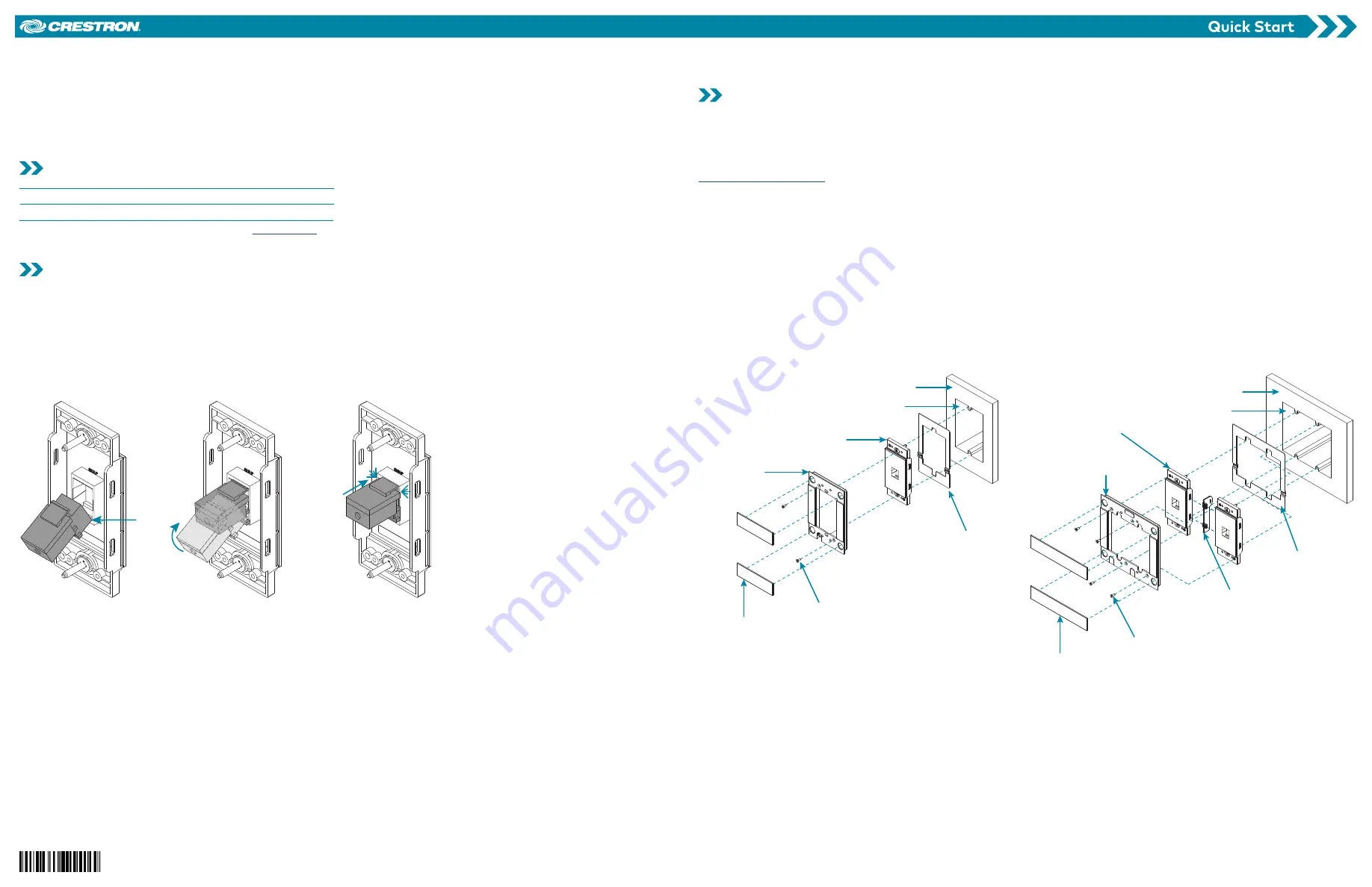
Install the Keystone Module
Make all necessary connections to the keystone module prior to installation. For details, refer to the documentation provided with the keystone
module.
To install the keystone module:
1.
Place the bottom lip of the keystone module over the bottom lip in the opening of the HZA-KEY.
2.
Tilt the keystone module up until the top of the module lines up with the rear of the HZA-KEY.
3.
Press the keystone module into the rear of the HZA-KEY. The keystone module snaps into place.
4.
For HZA-KEY2 and HZA-KEY4 wallplates, repeat steps 1 - 3 as necessary.
Step 1
Step 2
Step 3
Install the HZA-KEY
The HZA-KEY utilizes integrated mounting screws to secure it to the electrical box. The HZA-KEY must be paired with an HZ-FP faceplate (sold
separately) to complete the installation.
CAUTION:
Do not mix high- and low-voltage devices in the same electrical box without an approved barrier.
NOTE:
If the HZ-FP is not available at the time of installation, fold the wires into the electrical box and then secure the HZA-KEY to the electrical
box using the integrated mounting screws. When the faceplate is available for installation, refer to the HZ-FP Quick Start (Doc. 8286) at
www.crestron.com/manuals
.
1.
Turn the system power OFF.
NOTE:
For multi-gang installations, insert an alignment spacer (supplied with HZ-FP) between adjacent devices to maintain proper alignment
and spacing.
2.
Place the metal mounting bracket (supplied with HZ-FP) over the back of the HZA-KEY. The two-part metal bracket clips together which
allows the wiring to remain in place.
3.
Fold the wires into the electrical box.
4.
Secure the HZA-KEY to the electrical box using the integrated mounting screws on the device. To allow for adjustments, do not fully tighten
the screws at this time.
5.
Attach an HZ-FP to the HZA-KEY using the 4-40 x 1/4 in. faceplate mounting screws that are provided with the HZ-FP.
6.
Ensure that the HZA-KEY is properly aligned within the HZ-FP and then fully tighten the integrated mounting screws to secure the HZA-KEY
to the electrical box.
7.
Attach the magnetic top and bottom trim pieces (supplied with HZ-FP) to the HZ-FP.
8.
Turn the system power ON.
Single-Gang Installation
Wall
Electrical Box
(not supplied)
Metal Mounting
Bracket
(top and bottom,
not supplied)
HZA-KEY with
integrated mounting
screws
Faceplate
Mounting
Screws (x2)
(not supplied)
HZ-FP-G1
Faceplate
(not supplied)
Trim (x2)
(not supplied)
Multi-Gang Installation
Wall
Electrical Box
(not supplied)
Metal Mounting Bracket
(top and bottom,
not supplied)
Faceplate
Mounting
Screws (x4)
(not supplied)
HZ-FP-G2
Faceplate
(not supplied)
Trim (x2)
(not supplied)
Alignment Spacer
(supplied with
faceplate)
HZA-KEY with
integrated mounting
screws (x2)
NOTE:
HZ-FP2 shown. Installation is similar for HZ-FP-G3 and HZ-FP-G4.
HZA-KEY1/HZA-KEY2/HZA-KEY4
Keystone Wallplates


