background image


14  

  DMPS3-4K-200-C/300-C Series:  4K Presentation Systems 

Supplemental Guide – DOC. 7849B 

The OUTPUT push buttons consist of the following: 


Two HDMI push buttons numbered 1 and 2 


Two DM push buttons numbered 3 and 4 


Three LOCAL AUDIO push buttons labeled PROG, AUX 1, and AUX 2  

DMPS3-4K-350-C Routing Push Buttons  

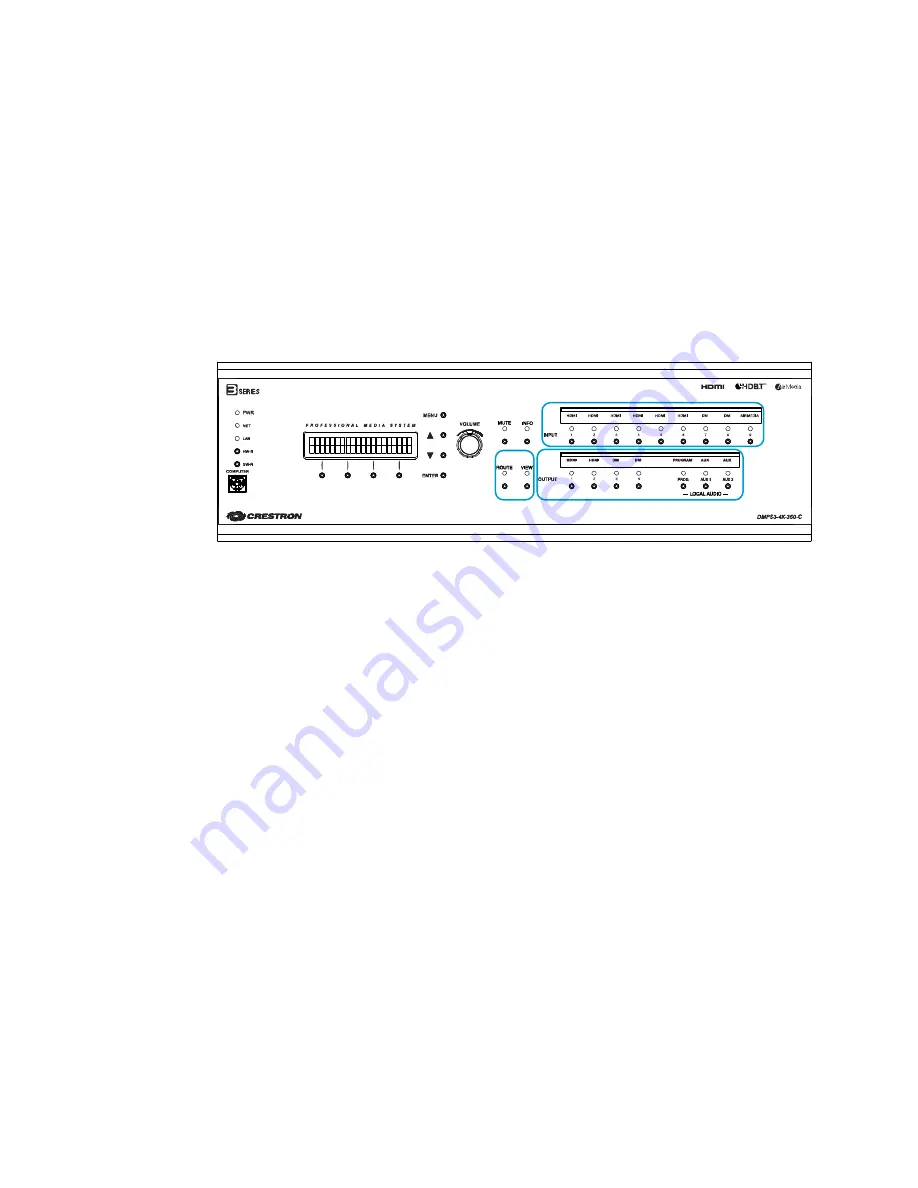
The DMPS3-4K-350-C provides a ROUTE push button, a VIEW push button, nine INPUT 
push buttons, seven OUTPUT push buttons, and corresponding LEDs as shown in the 

illustration below. 

DMPS3-4K-350-C Routing Push Buttons and LEDs  


The INPUT push buttons consist of the following: 


Six HDMI push buttons numbered 1


Two DM push buttons numbered 7 and 8 


One AIRMEDIA push button numbered 9 

The OUTPUT push buttons consist of the following: 


Two HDMI push buttons numbered 1 and 2 


Two DM push buttons numbered 3 and 4 


Three LOCAL AUDIO push buttons labeled PROG, AUX 1, and AUX 2  

Routing an Input to Outputs 

To route an input to one or more outputs using the routing push buttons, do the following: 

1.


Press the ROUTE push button. The ROUTE LED and the OUTPUT LEDs of any 
unrouted outputs light solid red. 

2.


Press the INPUT push button that corresponds to the input to be routed.  
The corresponding INPUT LED lights solid red to indicate that the input is selected, 
and the OUTPUT LEDs of the unrouted outputs turn off.  

3.


Press the desired OUTPUT push buttons. The OUTPUT LEDs of the selected 

outputs flash red. 

4.


Press ENTER to apply the route. The ROUTE and INPUT LEDs remain solid red, 
and the OUTPUT LEDs of the selected outputs light solid red. 

1

2

3

4

5

6

7

8

9

1

2

3

4

Summary of Contents for DMPS3-4K-250-C

Page 1: ...DMPS3 4K 200 C DMPS3 4K 300 C Series 3 Series 4K DigitalMedia Presentation Systems Supplemental Guide Crestron Electronics Inc ...

Page 2: ...ountries The HDBaseT Alliance logo is either a trademark or registered trademark of the HDBaseT Alliance in the United States and or other countries HDMI and the HDMI logo are either trademarks or registered trademarks of HDMI Licensing LLC in the United States and or other countries Other trademarks registered trademarks and trade names may be used in this document to refer to either the entities...

Page 3: ...Subnet Mask 5 Default Router 5 DHCP 5 Hostname 6 Domain Name 6 MAC Address 7 System ID 7 Configuring Control Settings 8 Backlight 8 Password 8 Info 9 Messages 9 Time Date 10 Front Panel 11 Using the Routing Push Buttons 12 DMPS3 4K 200 C Routing Push Buttons 12 DMPS3 4K 250 C Routing Push Buttons 13 DMPS3 4K 300 C Routing Push Buttons 13 DMPS3 4K 350 C Routing Push Buttons 14 Routing an Input to O...

Page 4: ......

Page 5: ...es the purchase and activation of a license refer to Answer ID 5652 in the Online Help section of the Crestron website www crestron com for detailed information Video outputs consist of one HDMI output and one DM 8G output Five balanced analog audio inputs are provided DMPS3 4K 300 C Provides matrix signal routing for up to eight video sources and four displays Video inputs consist of six HDMI inp...

Page 6: ...n about the built in AirMedia receiver of the DMPS3 4K 250 C and DMPS3 4K 350 C refer to the AirMedia Presentation Gateway Deployment Guide Doc 7693 Using the Front Panel LCD When the device is powered on the front panel LCD provides system bootup status information When the system bootup process is complete the LCD indicates the name of the device and the build version as shown in the sample scre...

Page 7: ...ove the cursor to the left if necessary press the button The default password is 12345 For information about changing the password refer to Password on page 8 3 Press ENTER to apply the password The Setup Menu opens Setup Menu Network Setup Navigating the Setup Menu To navigate the Setup Menu and submenus do the following To navigate upward in a menu or to move the cursor to the right when enterin...

Page 8: ... Available selections are as follows IP Address Subnet Mask Def Router DHCP Hostname Domain Name MAC Address System ID Each of the items on the Network Setup menu is discussed below IP Address By default DHCP Dynamic Host Configuration Protocol is enabled To view the current IP address or to set a static IP address do the following NOTE To be able to set a static IP address DHCP must be set to Off...

Page 9: ... following NOTE To be able to set a default router IP address DHCP must be set to Off For additional information refer to DHCP below 1 On the Network Setup menu select Def Router The current default router IP address appears on the LCD Def Router 000 000 000 000 If DHCP is set to Off continue with step 2 to set a default router IP address 2 Using the appropriate soft button under each octet in the...

Page 10: ...igits uppercase and lowercase letters and a hyphen To enter the characters in a hostname use the and buttons To move the cursor to the left press the soft button under the symbol To move the cursor to the right press the soft button under the symbol To delete a character position the cursor under the character to be deleted and then press the soft button under DEL To insert a space position the cu...

Page 11: ...etwork Setup menu select MAC Address A screen appears displaying the MAC address as shown in the sample below MAC Address 00 10 7f 8b 1e 9c System ID NOTE System ID numbers range from 1 to 64 The default system ID number is 1 It is recommended that the system ID always be changed to a number other than 1 NOTE A unique system ID must be assigned to the device whenever the device connects to the DM ...

Page 12: ...ect Backlight A screen appears allowing the desired brightness to be set Select Brightness Low 2 Using the or button select one of the following options Low Medium or High The default setting is Medium 3 Press ENTER to apply the selected setting An asterisk precedes the selected setting Password To change the password do the following 1 On the Control Setup menu select Password A screen appears al...

Page 13: ...ol to scroll to the right To scroll to the left press the soft button under the symbol To view all available items listed under REMS HD NET or OPS press the or button as appropriate Messages System messages are stored in a message log To view system messages do the following 1 On the Control Setup menu select Messages The SYSTEM LOG screen appears SYSTEM LOG Btm Clear 2 Do any of the following To ...

Page 14: ...played Use the or button to select the desired day iii To set the year press the soft button under YR Brackets enclose the year that is displayed Use the or button to select the desired year iv Press ENTER to apply the settings 3 To set the time do the following a Press the soft button under TIME A screen appears displaying the time TIME 10 38 07AM HR MIN AM PM b Do the following i To set the hour...

Page 15: ... ROUTE VIEW INPUT OUTPUT and LOCAL AUDIO buttons are disabled the MENU ENTER and soft buttons remain enabled To enable or disable the front panel controls do the following 1 On the Control Setup menu select Front Panel A screen appears allowing the front panel controls to be locked disabled or unlocked enabled Front Panel Lock On 2 Do either of the following To enable the front panel controls sele...

Page 16: ... 200 C DMPS3 4K 300 C Series and about using the push buttons to route an input to outputs Information about viewing routing status is also provided DMPS3 4K 200 C Routing Push Buttons The DMPS3 4K 200 C provides a ROUTE push button a VIEW push button seven INPUT push buttons five OUTPUT push buttons and corresponding LEDs as shown in the illustration below DMPS3 4K 200 C Routing Push Buttons and ...

Page 17: ...d 1 6 One DM push button numbered 7 One AIRMEDIA push button numbered 8 The OUTPUT push buttons consist of the following One HDMI push button numbered 1 One DM push button numbered 2 Three LOCAL AUDIO push buttons labeled PROG AUX 1 and AUX 2 DMPS3 4K 300 C Routing Push Buttons The DMPS3 4K 300 C provides a ROUTE push button a VIEW push button eight INPUT push buttons seven OUTPUT push buttons and...

Page 18: ...bered 9 The OUTPUT push buttons consist of the following Two HDMI push buttons numbered 1 and 2 Two DM push buttons numbered 3 and 4 Three LOCAL AUDIO push buttons labeled PROG AUX 1 and AUX 2 Routing an Input to Outputs To route an input to one or more outputs using the routing push buttons do the following 1 Press the ROUTE push button The ROUTE LED and the OUTPUT LEDs of any unrouted outputs li...

Page 19: ...tion Systems 15 Viewing Routing Status To view information about a route do the following 1 Press the VIEW button 2 Press the desired OUTPUT button The LCD displays the number of the selected output and the number of the input that is being routed to the selected output ...

Page 20: ...Crestron Electronics Inc Supplemental Guide DOC 7849B 15 Volvo Drive Rockleigh NJ 07647 2047259 Tel 888 CRESTRON 12 17 Fax 201 767 7576 Specifications subject to www crestron com change without notice ...

Reviews: