

DO
GUIDE
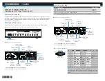
PC Connector Pin Assignments
DM-TX-401-S/DM-TX-401-S2
DigitalMedia 8G™ Fiber Transmitter 401
DO
Install the Device
The DM-TX-401-S and DM-TX-401-S2 can be placed on a flat surface, mounted into a rack, or
attached to the underside of a table. If rack mounting is desired, use the ST-RMK Rack Mount
Kit (sold separately). If under-table mounting is desired, use the UTK-1U-HALF Under-Table
Mounting Kit (sold separately).
DO
Connect the Device
Connect the device as appropriate for the installation (refer to illustrations
through
).
DM-TX-401-S and DM-TX-401-S2 Front Panel Connections (DM-TX-401-S Shown)
DM-TX-401-S Rear Panel Connections
DO
Check the Box
QTY PRODUCT
PART NUM.
1
Connector, 2-Pin
2003574
1
Connector, 5-Pin
2003577
1
Power Pack, 24 Vdc 0.75 A, 100-240 Vac
2045865
Not Included: Cables, Mounting Kits
Mouse/Keyboard Input
USB HID
RESET
DM
LINK
SETUP
AUTO VIDEO
HDMI
DISPLAY
PORT SELECT
DM-TX-401-S
PWR
PC
INPUT
10BASE-T/
100BASE-TX
Ethernet to Local
Network Device†
24V 0.75A
from Power Pack
(Included)
To DM
®
Switcher,
Receiver, or Other
DM Device
Unbalanced Stereo
Line Level
Audio Input
To Any
RS-232
Device
To IR Device
(e.g., Projector)
or Devices
without RS-232
Ground
DisplayPort
Digital Video/
Audio Input
HDMI
®
Digital Video/
Audio Input
RGB,
Component,
S-Video, or
Composite
Video Input
*
Composite
Video
Input
Unbalanced Stereo
Line Level Audio Input
*
Refer to illustration
for PC connector pin assignments.
† Refer to illustration
for LAN connector pin assignments.
MMF/SC
VID
PC
VIDEO IN
AUDIO IN
HDMI
DISPLAY PORT
L
R
G TX RX RS CS
L
I
N
K
C
O
M
CLASS 1
LASER
PRODUCT
DM OUT
IR
S G
24V
0.75A
LAN
G
10BASE-T/
100BASE-TX
Ethernet to Local
Network Device†
24V 0.75A
from Power Pack
(Included)
To DM Switcher,
Receiver, or Other
DM Device
Unbalanced Stereo
Line Level
Audio Input
To Any
RS-232
Device
To IR Device
(e.g., Projector)
or Devices
without RS-232
Ground
DisplayPort
Digital Video/
Audio Input
HDMI
Digital Video/
Audio Input
RGB,
Component,
S-Video, or
Composite
Video Input*
Composite
Video
Input
Unbalanced Stereo
Line Level Audio Input
*
Refer to illustration
for PC connector pin assignments.
† Refer to illustration
for LAN connector pin assignments.
VID
PC
VIDEO IN
HDMI
DISPLAY PORT
AUDIO IN
L
R
G TX RX RS CS
L
I
N
K
C
O
M
DM OUT
CLASS 1
LASER
PRODUCT
S G
IR
G
LAN
SMF/LC 24V
0.75A
DM-TX-401-S2 Rear Panel Connections
PIN NUM. RGB
YPbPr
S-VIDEO COMPOSITE
1
R
Pr
C
2
G
Y
Y
3
B
Pb
COMP
5
GND
GND
GND
GND
6
RED_GND
Pr_GND
C_GND
7
GRN_GND Y_GND
Y_GND
8
BLU_GND
Pb_GND
13
H
14
V
NOTE:
For best video performance, ground connections
should be kept separate. Do not connect ground wires to the
connector shell. The connector shell is reserved for the cable
shield.
Pin 10
Pin 5 Pin 1
Pin 6
Pin 15 Pin 11
5
1
11
15


