background image

Crestron 

CNX-B2/B4/B6/B8/B12


Single Gang Keypads


Operations & Installation Guide - DOC. 8173A 

Single Gang Keypads: CNX-B2/B4/B6/B8/B12  

  19 

NOTE

: In the symbol, the number of press and fbck (feedback)—outputs 

and inputs, respectively—correspond to the number of buttons in a given 
keypad. For example, a CNX-B8 has press1-8 and fbck1-8 only in its 
symbol. The illustration below shows the button arrangement for the 
keypads 

Button Arrangement of CNX-B Series Keypads (Front Views) 


Summary of Contents for CNX-B12

Page 1: ...Crestron CNX B2 B4 B6 B8 B12 Single Gang Keypads Operations Installation Guide...

Page 2: ...by the Technical Documentation department at Crestron Electronics Inc 15 Volvo Drive Rockleigh NJ 07647 1 888 CRESTRON All brand names product names and trademarks are the property of their respectiv...

Page 3: ...mming Software 14 Programming with Crestron AppBuilder or D3 Pro 15 Programming with SIMPL Windows 15 Programming with VT Pro e 21 Uploading and Upgrading 22 Communication Settings 23 Uploading a SIMP...

Page 4: ......

Page 5: ...ors almond black and white A letter at the end of the product name A B or W denotes the color i e CNX B12B is a black 12 button unit For simplicity within this guide the letter designating color is om...

Page 6: ...stomized single double and triple gang configurations Contact a Crestron customer service representative for details NOTE Temperature reading accuracy is affected by unit indicators and backlight stat...

Page 7: ...urce File Format projectname vtp Compiled File Format projectname hex Control System Update Files4 5 6 2 Series Control System Update Version C2 1001 CUZ or later CEN CN TVAV Update File Version 5 10...

Page 8: ...lus clearance for the wiring NOTE Crestron software and any files on the website are for Authorized Crestron dealers and Crestron Authorized Independent Programmers CAIP only New users may be required...

Page 9: ...Model White Color Black Color Keypad Overall Dimensions 2 912 in 4 762 in 12 096 cm 1 067 in 2 710 cm 1 536 in 3 902 cm Buttons 1 12 Side View Front View 5 568 cm LED window 1 2 12 NOTE Illustration i...

Page 10: ...it Detail View 1 788 in 4 158 in Rubber Membrane 4 541 cm 10 56 cm Indicator LED Speaker Cresnet port TOP NET 24 Y Z G 2 696 in 6 848 cm 1 696 in 4 301 cm Front View with buttons removed Back View Ins...

Page 11: ...e Crestron warranty NOTE When installing network wiring refer to the latest revision of the wiring diagram s appropriate for your specific system configuration available from the Downloads Product Man...

Page 12: ...is the Y conductor and the Z conductor NOTE When daisy chaining Cresnet units strip the ends of the wires carefully to avoid nicking the conductors Twist together the ends of the wires that share a pi...

Page 13: ...d be the only network device connected to the control system Method B Touch Settable IDs which begins on page 10 applies to keypads with firmware version 1 06 or later in a Cresnet system with 2 Serie...

Page 14: ...ore using this method you should have a list of all current network devices and their Net IDs to avoid assigning duplicate IDs Set Net ID via D3 Pro Version 1 0 of this program includes procedures tha...

Page 15: ...Network Devices the first eight digits of each line constitute the TSID number hexadecimal form of the serial number Set Net ID by TSID Window Serial Number to TSID Conversion If you know the device s...

Page 16: ...d Two 1 in pan head Phillips screws supplied Insulation not supplied NOTE The insulation will protect the sensor from any in wall conditions such as drafts etc Use type in compliance with local codes...

Page 17: ...and faceplate orient with arrow up Make sure faceplate snaps in position 8 Turn Cresnet system power ON NOTE The heat from the button LEDs can affect the reading of the temperature sensor Thus the ac...

Page 18: ...he capabilities of the system is very easy Crestron AppBuilder and SIMPL Windows are intended for users with different levels of programming knowledge Crestron AppBuilder is easier to use for the begi...

Page 19: ...conferencing and lighting The interface of this tool guides you through a few basic steps for designating rooms and specifying the control system touchpanels devices and functionality Crestron AppBuil...

Page 20: ...m the Device Library In Configuration Manager drag the PRO2 from the Control Systems folder of the Device Library and drop it in the upper pane of the System Views The PRO2 with its associated communi...

Page 21: ...into the upper pane of System Views Additional units are assigned different NET ID numbers as they are added C2Net Device Slot 9 Setting the Net ID in Device Settings Double click the CNX B12 icon in...

Page 22: ...dded to a program if a duplicate device or a device with the same NET ID already exists in the program Always ensure that the hardware and software settings of the NET ID match For NET ID hardware set...

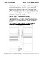
Page 23: ...NOTE In the symbol the number of press and fbck feedback outputs and inputs respectively correspond to the number of buttons in a given keypad For example a CNX B8 has press1 8 and fbck1 8 only in it...

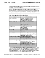
Page 24: ...ontrols temperature format High 1 Celsius Low 0 Fahrenheit BackliteON Activates backlight High 1 On Low 0 Off Sound20 120 Activates sound file specified by the corresponding join number in VT Pro e Ri...

Page 25: ...Search for CNX B12 SMW Programming with VT Pro e The CNX B12 is capable of playing audio messages as system prompts and responses These files are recorded as WAV files on a PC using an audio utility...

Page 26: ...ns or functions NOTE When you begin to create a new keypad program note that you cannot assign pages or sub pages because keypads have no screen Instead use Tools Sound Manager from the VT Pro e menu...

Page 27: ...nctions are accessed through the commands and options in the Viewport menus Therefore for its effectiveness as a support and diagnostic tool the Crestron Viewport may be preferred over development too...

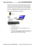
Page 28: ...of the Crestron website www crestron com Refer to the figure below for a typical connection diagram when uploading files Note Use a standard DB9 male to female straight through cable Typical Connecti...

Page 29: ...Communications Settings Command 4 Select RS 232 as the connection type Verify that an available COM port COM 1 is shown after this step is selected and that all communication parameters and necessary...

Page 30: ...ngs for a 2 Series control system Consult the Operations Guide for the control system being used for exact parameter selection 5 To verify communication select Diagnostics Establish Communications Fin...

Page 31: ...rify that the procedure for Communication Settings that begins on page 23 has been performed 2 As shown after this step select File Transfer Send Program alternatively press Alt P from the Viewport me...

Page 32: ...File Project The CNX B12 keypad source file has the extension vtp A compiled VT Pro e file has the extension hex The VT Pro e project file can be uploaded to the keypad using VT Pro e or via the Cres...

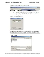
Page 33: ...Transfer Send Touchpanel Command 3 As shown after this step select the NET ID of the CNX B12 keypad and then click OK The Open window appears refer to graphic below Select Network ID Window NOTE When...

Page 34: ...updates asp for the latest version of firmware Not every product has a firmware upgrade but as Crestron improves functions adds new features and extends the capabilities of its products firmware upgra...

Page 35: ...oject firmware lower the port speed baud rate to 38400 to match the Cresnet bus speed Open Window NOTE Firmware upgrades to the button panel include two files filename a csf and filename b csf Select...

Page 36: ...1 Open the Crestron Viewport 2 From the Viewport menu select Functions Assign Serial Number The Serial Number Assignment window appears Serial Number Assignment Window 3 Enter the device serial numbe...

Page 37: ...ork F4 to verify Net ID Keypad Net ID is not set to match the Net ID set in the SIMPL Windows program Verify SIMPL Windows program for setting Net ID Keypad Net ID is the same as another device s Net...

Page 38: ...n Asia call Crestron Asia at 852 2341 2016 In Latin America call Crestron Latin America at 5255 5093 2160 In Australia and New Zealand call Crestron Control Solutions at 61 2 9737 8203 Future Updates...

Page 39: ...ding but not limited to using the Software a either directly or through commands data or instructions from or to another computer b for local campus or wide area network internet or web hosting servic...

Page 40: ...stantially in accordance with the published specifications for a period of ninety 90 days from the date of receipt and b that any hardware accompanying the Software will be subject to its own limited...

Page 41: ...play and overlay components are covered for 90 days batteries and incandescent lamps are not covered This warranty extends to products purchased directly from CRESTRON or an authorized CRESTRON dealer...

Page 42: ...Single Gang Keypads Crestron CNX B2 B4 B6 B8 B12 38 Single Gang Keypads CNX B2 B4 B6 B8 B12 Operations Installation Guide DOC 8173A This page intentionally left blank...

Page 43: ...Crestron CNX B2 B4 B6 B8 B12 Single Gang Keypads Operations Installation Guide DOC 8173A Single Gang Keypads CNX B2 B4 B6 B8 B12 39 This page intentionally left blank...

Page 44: ...estron Electronics Inc Operations Installation Guide DOC 8173A 15 Volvo Drive Rockleigh NJ 07647 03 03 Tel 888 CRESTRON Fax 201 767 7576 Specifications subject to www crestron com change without notic...

Reviews: