Crestron
CNRACKX-DP
CNX Dual Processor Modular Control System
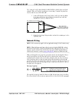
Two “rack ears” are provided with the CNRACKX-DP so that the unit can be rack
mounted. These ears must be installed prior to mounting. Complete the procedure
below to attach ears to CNRACKX-DP:
1. At the left-front side of the unit, position a rack ear so that its drilled
holes align with the four unused holes and secure the ear with four
supplied #6-32 screws, as shown below.
Ear Attachment for Rack Mounting
SECURE WITH
FOUR #6-32 SCREWS
PER EAR (SUPPLIED)
2. Repeat the first step of this procedure to attach the remaining ear to the
right-front side.
Network Wiring
NOTE:
This section only applies to those applications using 4-wire Cresnet wiring.
NOTE:
When making connections to the 4-wire port labeled CRESNET, refer to
the latest revision of the Cresnet Network Interconnect Drawing (Doc. 5411). This
document can be obtained from the Downloads page (CABLES and MANUALS
Libraries) of Crestron’s website (
. Search for CRESNET.PDF.
When calculating the wire gauge for a particular network run, the length of the run
and the power factor of each network unit to be connected must be taken into
consideration. If network units are to be daisy-chained on the run, the power factor
of each network unit to be daisy-chained must be added together to determine the
power factor of the entire chain. The length of the run in feet and the power factor of
the run should be used in the following resistance equation to calculate the value on
the right side of the equation.
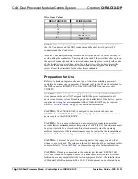
Resistance Equation
R = Resistance (refer to table below).
L = Length of run (or chain) in feet.
PF = Power factor of entire run (or chain).
R < L x PF
40,000
Where:
The required wire gauge should be chosen such that the resistance value is less than
the value calculated in the resistance equation. Refer to the table after this paragraph.
Operations Guide - DOC. 8151
CNX Dual Processor Modular Control System: CNRACKX-DP
•
9


