About the Sound Blaster Audigy Card and external Audigy Drive 1-4
Your External
Audigy Drive
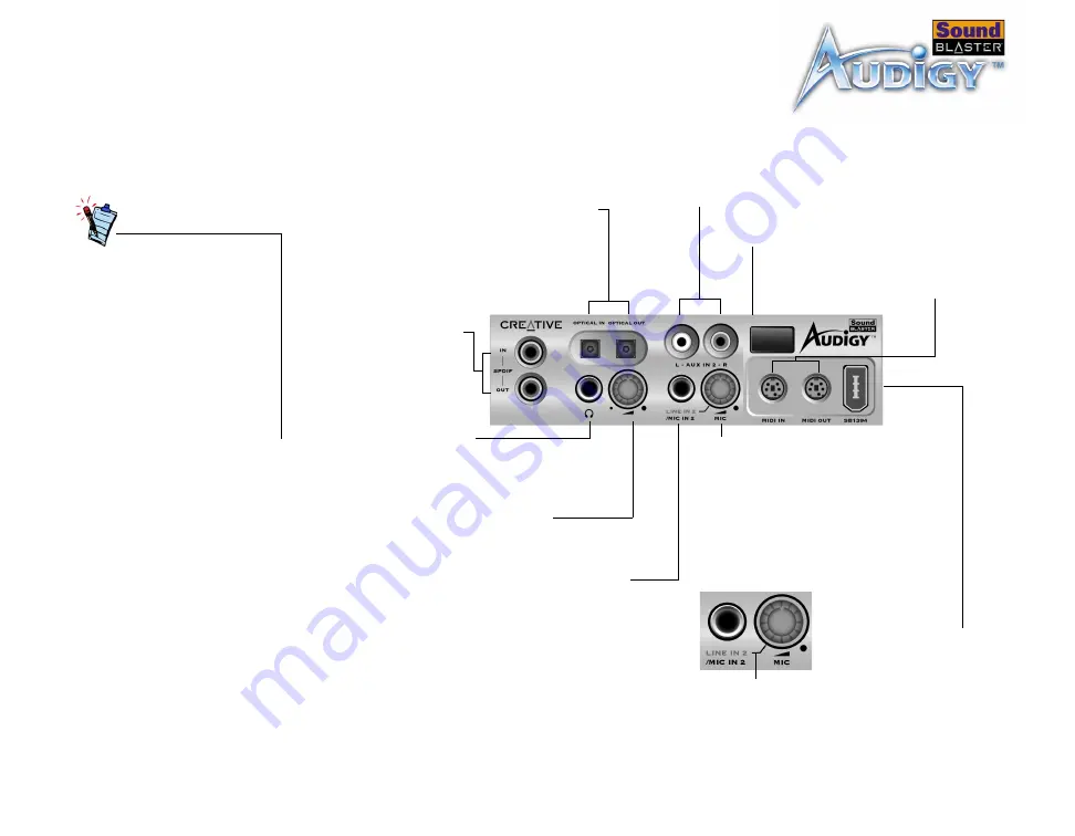
The front panel of your external Audigy Drive has these jacks, connectors and
controls:
• To connect your existing
computer headphones and
microphone to the
external Audigy Drive, use
a 3.5 mm minijack to ¼”
jack adapter.
• Set the gain level of the
Mic In 2 jack to the
minimum before
connecting or turning on a
microphone, especially if
you are using headphones.
MIDI In/Out connectors
Connects to MIDI devices using
the Mini DIN-to-Standard DIN
adapter provided.
Line In 2/Mic In 2 selector
knob(Microphone Gain Control)
To switch to Line In 2, turn the knob counter
clockwise over the Line In 2/Mic In 2
separator mark until you hear a “click” sound.
To switch back to Mic In 2, turn the knob
clockwise over the separator mark until you
hear a “click” sound. To control the
microphone gain, continue to turn clockwise.
See “Adjusting Headphones Volume and
¼” Line In 2/Mic In 2 jack
Connects to high-quality dynamic
microphones or audio devices such as
electric guitars and DAT or MiniDisc
players.
RCA Auxiliary In jacks
Connects to consumer equipment such as VCRs,
TVs and CD players, via RCA Auxiliary outputs.
Optical SPDIF In/Out connectors
Connects to digital audio devices such
as DAT and MiniDisc recorders, via
optical input/output.
Headphones Volume control knob
Controls the headphones output volume.
See “Adjusting Headphones Volume and
RCA SPDIF In/Out
jacks
Connects to digital audio
devices such as DAT and
MiniDisc recorders, via
RCA input/output.
¼” Headphones jack
Connects to a pair of high-quality
headphones. Your speaker output
is muted when you connect the
headphones to the drive.
Figure 1-3: Jacks, connectors and controls on the external Audigy Drive.
Line In 2/Mic In 2
separator mark
Infrared Receiver
Lets you control your computer using
the IR remote control.
SB1394 connector
Connects to IEEE1394
compatible devices.


