


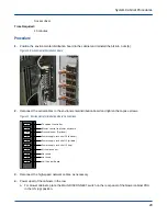


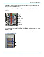


Figure 6. Operator Interface
Operator
interface
Serial cable
4 nuts
2.4.2
Install an Operator Interface
Prerequisites
Tools Required:
Small Phillips screwdriver
5/16-in. socket
Socket driver
Time Required:
15 minutes
About this task
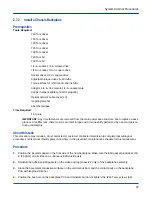
The X and Y cabinet address information, cabinet type, and coordinated cooling region (CCR) position is stored
on the cabinet controller backplane SEEP. This information does not need to be reset when replacing the operator
interface.
Procedure
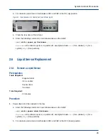
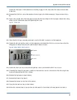
1. Position the operator interface in the cabinet and reinstall the 5/16-in. nuts (4).
Figure 7. Operator Interface
Operator
interface
Serial cable
4 nuts
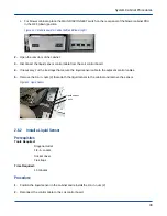
2. Reconnect the serial cable to the operator interface and tighten the small captive Phillips screws (2).
3. Reconnect all disconnected high-speed network cables.
4. Power up all of the cabinets in the row.
a. For blower cabinets, place the MAIN DISCONNECT switch on the rear panel of the blower cabinet PDU
in the ON (up) position.
System Cabinet Procedures
25