background image

A Crane Co. Company

BARNES

BARNES

®

INSTALLATION and OPERATION MANUAL

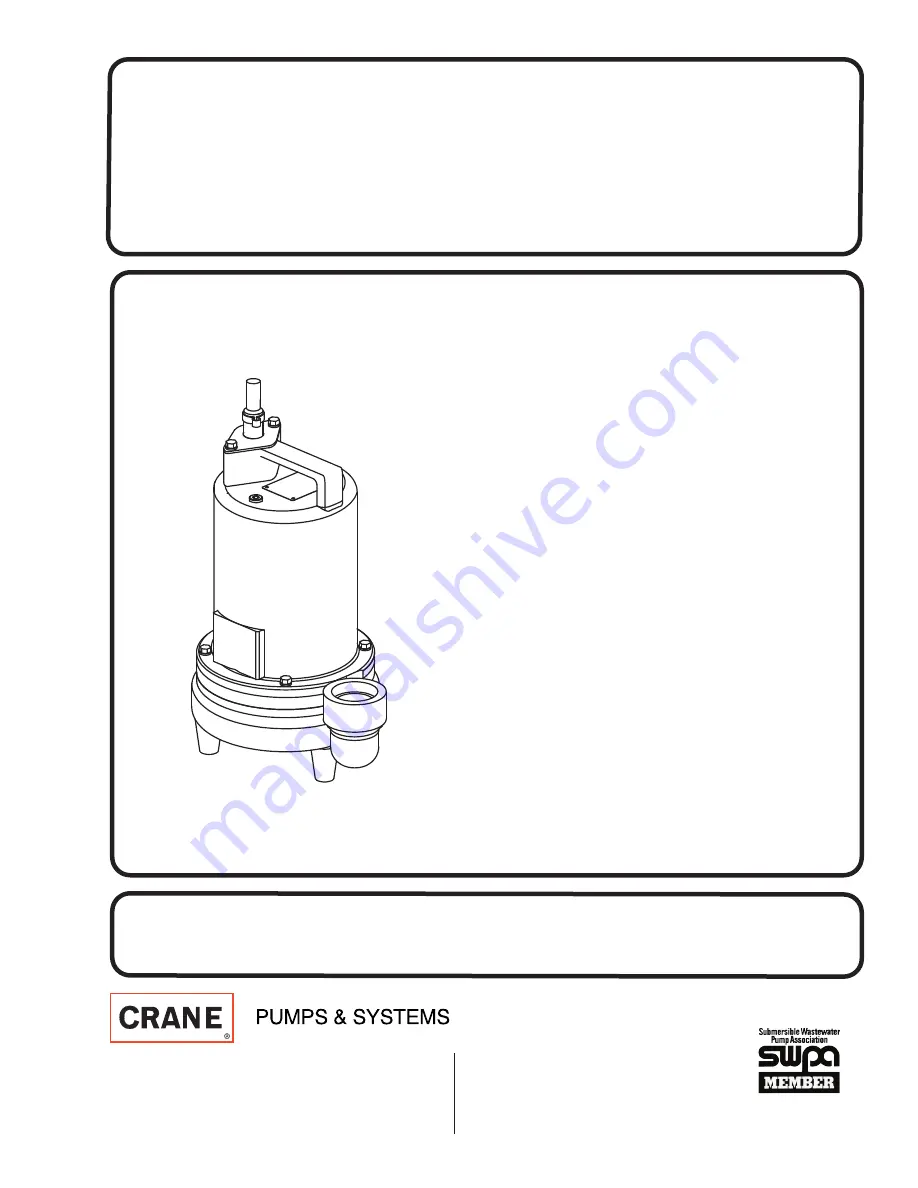
Submersible Effluent Pumps

IMPORTANT! 

Read all instructions in this manual before operating pump.


As a result of Crane Pumps & Systems, Inc., constant product improvement program,


product changes may occur. As such Crane Pumps & Systems reserves the right to 


change product without prior written notification.

420 Third Street   


83 West Drive, Bramton

Piqua, Ohio 45356 


Ontario, Canada L6T 2J6

Phone: (937) 778-8947 


Phone: (905) 457-6223

Fax: (937) 773-7157 


Fax: (905) 457-2650

www.cranepumps.com

Form No. 106991-Rev. U

Series: EH-HT

0.5 & 1.5 HP, 3450 RPM, 60 Hz.

High Temperature

Summary of Contents for BARNES EH-HT Series

Page 1: ...stant product improvement program product changes may occur As such Crane Pumps Systems reserves the right to change product without prior written notification 420 Third Street 83 West Drive Bramton Piqua Ohio 45356 Ontario Canada L6T 2J6 Phone 937 778 8947 Phone 905 457 6223 Fax 937 773 7157 Fax 905 457 2650 www cranepumps com Form No 106991 Rev U Series EH HT 0 5 1 5 HP 3450 RPM 60 Hz High Tempe...

Page 2: ...D VIEW Fig 14 16 PARTS LIST 17 18 RETURNED GOODS POLICY 13 WARRANT 20 START UP REPORT 21 22 WARRANTY REGISTRATION SPECIAL TOOLS AND EQUIPMENT INSULATION TESTER MEGGER DIELECTRIC TESTER SEAL TOOL KIT see parts list PRESSURE GAUGE KIT see parts list Other brand and product names are trademarks or registered trademarks of their respective holders Barnes is a registered trademark of Crane Pumps System...

Page 3: ...ert fingers in pump with power connected Always wear eye protection when working on pumps Make sure lifting handles are securely fastened each time before lifting DO NOT operate pump without safety devices in place Always replace safety devices that have been removed during service or repair Secure the pump in its operating position so it can not tip over fall or slide DO NOT exceed manufacturers ...

Page 4: ...240Volt Capacitor Start Induction Run Includes Overload Protection in Motor 1 5HP Permanent Split Capacitor PSC Includes Overload Protection in Motor THREE PHASE 200 240 480 is Tri Voltage 600V Requires Overload Protection to be included in control panel OPTIONAL EQUIPMENT Seal Material Impeller Trims Additional cord Normally Closed Temperature Sensors with cord for 3 phase pumps Requires relay in...

Page 5: ...sentative or Crane Pumps Systems Inc Service Department in Piqua Ohio telephone 937 778 8947 or Crane Pumps Systems Canada in Brampton Ontario 905 457 6223 SECTION C INSTALLATION C 1 Location These pumping units are self contained and are especially designed to handle septic tank effluent nonexplosive or noncorrosive liquids and shall NOT be installed in locations classified as hazardous in accord...

Page 6: ...ic Plug float cord into outlet then plug pump cord into float cord Manual Plug pump cord directly into outlet C 4 Electrical Connections An acceptable motor control switch shall be provided at the time of installation C 4 1 Power and Control Cable The cord assembly mounted to the pump must not be modified in any way except for shortening to a specific application Any splice between the pump and th...

Page 7: ...entarily applying power D 2 2 Incorrect Rotation for Single Phase Pumps In the unlikely event that the rotation is incorrect for a single phase pump contact a Barnes Pumps Service Center D 3 Start Up Report Included at the end of this manual are two start up report sheets these sheets are to be completed as applicable Return one copy to Barnes Pumps and store the second in the control panel or wit...

Page 8: ...3 Pressure Test Pumps that have been disassembled Motor Housing If the pump has been disassembled the oil should be drained before a pressure test as described in section F 1 1 Remove pipe plug 39 from motor housing 6 Apply pipe sealant to pressure gauge assembly and tighten into hole See Figure 2 Pressurize motor housing to 10 P S I Use soap solution around the sealed areas and inspect joints for...

Page 9: ... impeller and motor housing on volute 1 Position lockwasher 12 on cap screw 26 and screw into volute 1 Torque to 100 in lbs Check for free rotation of motor and impeller F 3 Shaft Seal Service CAUTION Handle seal parts with extreme care DO not scratch or mar lapped surfaces F 3 1 Disassembly and Inspection To expose shaft seal 28 for examination disassemble volute and impeller as outlined in parag...

Page 10: ...ousing 6 using a T bolt or a pair of pliers and a 25 20 screw in the threads of the terminal block 21 Be sure to leave slack on the motor leads connected underneath Use needle nose pliers to pull each female connector off of the pins on the underside of the terminal block 21 see Figure 8 The unit voltage should be noted Repeat cable and terminal block removal procedure for any control cables 56 if...

Page 11: ... independent of the terminal block as shown using connectors 48 and wire assemblies 49 as required Do not use wire nuts Slip motor leads and ground wire through fiberglass sleeve Lower motor housing 6 down onto seal plate 5 while aligning holes and stringing motor leads through the cable entry bore s Slipping cords inside a 1 ft length of 5 conduit makes this easier Place socket head cap screws 47...

Page 12: ...12 FIGURE 12 ...

Page 13: ...e serial number block will consist of a six digit number which is specific to each pump and may be preceded by a alpha character which indicates the plant location This number will also be suffixed with a four digit number which indicates the date the unit was built Date Code EXAMPLE A012345 0490 Reference the six digit portion Serial Number of this number when referring to the product RETURNED GO...

Page 14: ...k cutter for freedom of operation security and condition Clean cutter and inlet of any obstruction 9 Loosen union slightly to allow trapped air to escape Verify that turn off level of switch is set so that the suction is always flooded Clean vent hole 10 Remove examine for damage Replace pump stator if required 11 Repair fixtures as required to eliminate leakage 12 Check pump temperature limits fl...

Page 15: ...15 FIGURE 13 ...

Page 16: ...16 FIGURE 14 ...

Page 17: ... Cable Set 16a 1 103582 Compression Flange Included with cable 19 1 105197 Snap Ring Std 2 105197 Snap Ring Optional for Temp sensors 20 1 2 31051 224 O ring Std 2 2 31051 224 O ring Optional for Temp sensors 21 1 103584 Terminal Block 1 Phase 103583 3 Phase 22 1 105111 Ground Wire Assembly Std 2 105111 Ground Wire Assembly Optional for Temp sensors 23 1 016660 Screw 8 32 x 375 Lg 24 1 085326 Reta...

Page 18: ...temperature sensor 51 2 105155 Wire Assembly Optional for temperature sensor 52 2 625 00163 Terminal Connector Optional for temperature sensor 54 1 103584 Terminal Block Temperature sensor options 56 1 See Table 2 Control Cable Optional for Temp sensors 65 1 625 02117 Sleeve Fiberglass 66 1 030068 Jam Nut 20 S S 67 A R Loctite 603 TABLE 2 POWER CABLE SENSOR CABLE SETS CABLE LENGTH ITEM 16 1 Phase ...

Page 19: ...es between the results of field testing conducted by or for user and laboratory tests corrected for field performance the latter shall control RECOMMENDATIONS FOR SPECIAL APPLICATIONS OR THOSE RESULTING FROM SYSTEMS ANALYSES AND EVALUATIONS WE CONDUCT WILL BE BASED ON OUR BEST AVAILABLE EXPERIENCE AND PUBLISHED INDUSTRY INFORMATION SUCH RECOMMENDATIONS DO NOT CONSTITUTE A WARRANTY OF SATISFACTORY PE...

Page 20: ...d Or Decontaminated As Necessary Prior To Shipment To Insure That Employees Will Not Be Exposed To Health Hazards In Handling Said Material All Applicable Laws And Regulations Shall Apply IMPORTANT WARRANTY REGISTRATION Your product is covered by the enclosed Warranty If you have a claim under the provision of the warranty contact your local Crane Pumps Systems Inc Distributor ...

Page 21: ...Does impeller turn freely by hand Yes No Condition of equipment Good Fair Poor Condition of cable jacket Good Fair Poor Resistance of cable jacket Good Fair Poor Resistance of cable and pump motor measured at pump control Red Black Ohms Red White Ohms White Black Ohms Resistance of Ground Circuit between Control Panel and outside of pump Ohms MEG Ohms check of insulation Red to Ground White to Gro...

Page 22: ...tion Pump Off L1 L2 L2 L3 L3 L1 Voltage supply at panel line connection Pump On L1 L2 L2 L3 L3 L1 Amperage Load connection Pump On L1 L2 L3 FINAL CHECK Is pump seated on discharge properly Check for leaks Does check valve s operate properly Flow Does station appear to operate at proper rate Pump down time Noise level High Medium Low Comments Equipment difficulties during start up MANUALS Has opera...

Reviews: