background image

10

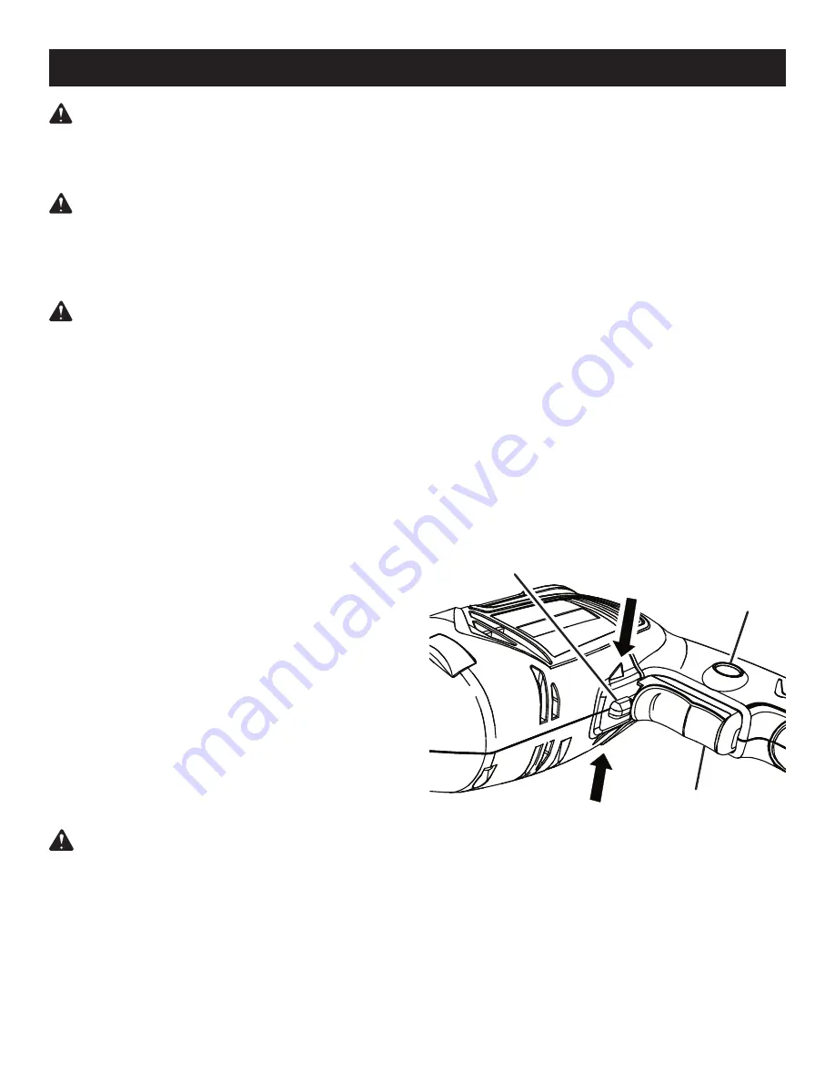
DIRECTION OF ROTATION SELECTOR

(FORWARD/REVERSE)

See Figure 2.

The direction of bit rotation is reversible and is controlled 
by a selector located above the switch trigger. With the 
drill held in normal operating position, the direction of 
rotation selector should be positioned to the left of the 
switch trigger for drilling. The drilling direction is reversed 
when the selector is to the right of the switch trigger. 

CAUTION:


To prevent gear damage, always allow 

the chuck to come to a complete stop before chang-
ing the direction of rotation. 

To stop the drill, release the switch trigger and allow the 
chuck to come to a complete stop.

SPINDLE LOCK

The spindle lock allows the user to keep the chuck from 
turning while changing bits and chucks.

WARNING

:


Do not allow familiarity with tools

to make you careless. Remember that a careless 
fraction of a second is sufficient to inflict serious 
injury.

WARNING

:


Always wear safety goggles or safety 

glasses with side shields when operating power 
tools. Failure to do so could result in objects being 
thrown into your eyes resulting in possible serious 
injury.

WARNING

Do not attempt to modify this tool 

or create accessories not recommended for use 
with this tool. Any such alteration or modification is 
misuse and could result in a hazardous condition 
leading to possible serious personal injury.

APPLICATIONS

You may use this tool for the purposes listed below:

Drilling in wood

�Drilling in ceramics, plastics, fiberglass, and laminates

�Drilling in both hard and soft metals

Using driving accessories, such as driving screws with 
screwdriver bits����

Mixing paint

SWITCH TRIGGER

See Figure 2.

To turn the drill ON, depress the switch trigger. To turn it 

OFF

, release the switch trigger.

VARIABLE SPEED

The variable speed switch trigger delivers higher speed 
and torque with increased trigger pressure and lower 
speed with decreased trigger pressure.

NOTE: 

You might hear a whistling or ringing noise from 

the switch during use. Do not be concerned; this is a nor-
mal part of the switch function.

KEYLESS CHUCK

See Figure 2.

The keyless chuck is used to install and remove bits.

WARNING:


Do not hold the chuck body with one 

hand and use the power of the drill to tighten the 
chuck jaws on the drill bit. The chuck body could slip 
in your hand, or your hand could slip and come in 
contact with the rotating drill bit. This could cause an 
accident resulting in serious personal injury.

Fig. 2

SWITCH 

TRIGGER

OPERATION

DIRECTION OF 

ROTATION SELECTOR

REVERSE

FORWARD

LOCK-ON 

BUTTON

Summary of Contents for 315.101140

Page 1: ...932 3188 Sears Roebuck and Co 3333 Beverly Rd Hoffman Estates IL 60179 USA Visit the Craftsman web page www sears com craftsman Save this manual for future reference WARNING To reduce the risk of injury the user must read and understand the operator s manual before using this product 983000 730 11 14 05 REV 00 ...

Page 2: ...N IT TO THE NEAREST SEARS STORE IN THE UNITED STATES and Sears will replace it free of charge If this Craftsman tool is used for commercial or rental purposes this warranty applies for only 90 days from the date of purchase This warranty gives you specific legal rights and you may also have other rights which vary from state to state Sears Roebuck and Co Dept 817 WA Hoffman Estates IL 60179 INTROD...

Page 3: ...accidents n Remove any adjusting key or wrench before turning the power tool on A wrench or a key left attached to a rotating part of the power tool may result in personal injury n Do not overreach Keep proper footing and balance at all times This enables better control of the power tool in unexpected situations n Dress properly Do not wear loose clothing or jew elry Keep your hair clothing and gl...

Page 4: ...tion When using an extension cord be sure to use one heavy enough to carry the current your product will draw A wire gauge size A W G of at least 14 is recommended for an extension cord 50 feet or less in length A cord exceeding 100 feet is not recom mended If in doubt use the next heavier gauge The smaller the gauge number the heavier the cord An undersized cord will cause a drop in line volt age...

Page 5: ... injury user must read and understand operator s manual before using this product Eye Protection Always wear safety goggles safety glasses with side shields or a full face shield when operating this product Precautions that involve your safety Failure to keep your hands away from the blade will result in serious personal injury Failure to keep your hands away from the blade will result in serious ...

Page 6: ...beginning power tool operation always wear safety goggles safety glasses with side shields or a full face shield when needed We recommend Wide Vision Safety Mask for use over eyeglasses or standard safety glasses with side shields Always use eye protection which is marked to comply with ANSI Z87 1 WARNING SAVE THESE INSTRUCTIONS The following signal words and meanings are intended to explain the l...

Page 7: ...heck the power supply EXTENSION CORDS When using a power tool at a considerable distance from a power source be sure to use an extension cord that has the capacity to handle the current the tool will draw An undersized cord will cause a drop in line voltage resulting in overheating and loss of power Use the chart to deter mine the minimum wire size required in an extension cord Only round jacketed...

Page 8: ...le levels are recessed in the motor housing and are used to keep drill bits level during both horizontal and vertical drilling operations VARIABLE SPEED The variable speed switch trigger delivers higher speed with increased trigger pressure and lower speed with de creased trigger pressure DIRECTION OF ROTATION SELECTOR FORWARD REVERSE Your drill has a direction of rotation forward reverse selector...

Page 9: ...ing please call 1 800 932 3188 for assistance PACKING LIST Drill Case Operator s Manual WARNING If any parts are missing do not operate this tool until the missing parts are replaced Failure to do so could result in possible serious personal injury WARNING Do not attempt to modify this tool or create accessories not recommended for use with this tool Any such alteration or modification is misuse a...

Page 10: ... accessories not recommended for use with this tool Any such alteration or modification is misuse and could result in a hazardous condition leading to possible serious personal injury APPLICATIONS You may use this tool for the purposes listed below n Drilling in wood n Drilling in ceramics plastics fiberglass and laminates n Drilling in both hard and soft metals n Using driving accessories such as...

Page 11: ...om the drill resulting in possible serious personal injury or damage to the chuck NOTE Rotate the chuck body in the direction of the arrow marked LOCK to tighten the chuck jaws n Rotate the chuck clockwise to tighten the chuck jaws securely on the bit n Rotate the chuck body slightly to release the spindle lock Fig 4 WRONG INSTALLING BITS See Figures 3 4 n Unplug the drill n Depress the spindle lo...

Page 12: ... a hole WARNING Be prepared for binding at bit break through When these situations occur drill has a tendency to grab and kick opposite to the direction of rotation and could cause loss of control when breaking through material If not prepared this loss of control can result in possible serious injury When drilling metals use a light oil on the drill bit to keep it from overheating The oil will pr...

Page 13: ...pes of materials However if you do work with any of these materials it is extremely important to clean the tool using compressed air LUBRICATION All of the bearings in this tool are lubricated with a suffi cient amount of high grade lubricant for the life of the unit under normal operating conditions Therefore no further lubrication is required Only the parts shown on the parts list are intended t...

Page 14: ...el number in all correspondence regarding your DRILL or when ordering repair parts Key Part No Number Description Qty 1 690033055 Chuck 1 2 940057059 Data Plate 1 3 940005055 Logo Plate 1 4 300912234 Carrying Case not shown 1 983000730 Operator s Manual 1 3 2 Note The assembly shown represents an important part of the double insulated system To avoid the possibility of alteration or damage to the ...

Reviews: