Cosel SFS152412C Instruction Manual Download Page 6

7 Safety Considerations

¡

To apply for safety standard approval using this power supply, the 
following conditions must be met.

¿

This unit must be used as a component of the end-use equipment.

¿

The equipment does neither contain any basic nor double / rein-

forced insulation between input and output.
If the input voltage is greater than 60VDC, this has to be provided 
by the end-use equipment according to the final build in condition.

¿

Safety approved fuse must be externally installed on input side.
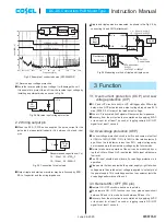
8   Temperature   

Measuring Point

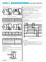
9.1 Delivery package information (SFS series 

SMD type)

¡

These are packed in a tray (Fig.9.1, 9.2).

¡

Capacity of the tray is 15 max.
In case of fractions, the units are stored in numerical order.

9 SMD type Package Information

DC-DC Converters PCB Mount Type

Instruction Manual

¡

In case of forced air, ventilation must keep the temperature of 
point A and B below 120

C

. Refer to Fig.8.1 for the location of 

point A and B.

Fig.8.1 Location of point A and B

Point B

Point A

Fig.9.1 Delivery package information(SFS10/SFS15/SFS20)

Fig.9.2 Delivery package information(SFS30)

Dimension in mm
Material : Conductive PS

Dimension in mm
Material : Conductive PS

9.3

45

40

X

4=160

55

X

2=110

250

200

45

3

2

9

8

6

5

12

11

7

4

10

15

14

13

12

50.4

X

2=100.8

49.6

40.2

X

4=160.8

44.6

200

250

2

3

5

6

4

11

12

14

15

10

13

7

8

9

SFS/SFCS-24

June 26, 2020

Summary of Contents for SFS152412C

Page 1: ...g Input Output Pin SFS SFCS 20 2 1 Wiring input pin SFS SFCS 20 2 2 Wiring output pin SFS SFCS 21 4 Series and Parallel Operation SFS SFCS 23 4 1 Series operation SFS SFCS 23 4 2 Parallel operation SF...

Page 2: ...ore than the value indicated above 3 Conducted noise Install an external input filter as shown in Fig 2 2 in order to re duce conducted noise The result for this solution is shown in Fig 2 3 C1 1 F ce...

Page 3: ...may be increased more than maximum voltage by the failure mode Normal or abnormal operation of the unit can be monitored by us ing the ALM pin When OVP is activated ALM signal will become low level Th...

Page 4: ...or abnormal operation of the unit can be monitored by us ing the ALM pin When OVP or LVP are activated ALM pin becomes same level as Vin pin The sink current of ALM pin is 10mA max 3 7 Isolation For...

Page 5: ...ecommended at 125C if unpacked products was kept under uncontrol condition in which 30C 60 RH or higher Original tray is not heat resistant please move them to heat resistant tray preparing to bake th...

Page 6: ...SMD type These are packed in a tray Fig 9 1 9 2 Capacity of the tray is 15 max In case of fractions the units are stored in numerical order 9 SMD type Package Information DC DC Converters PCB Mount Ty...

Page 7: ...order Do not cut or deform the tray Tray is stacked with alternating opposite direction to prevent prod ucts from contacting against the bottom of trays Do not cut or deform the tray DC DC Converters...

Reviews: