

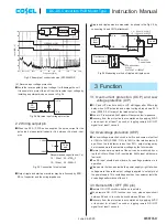


(4) Reverse input voltage protection
¡
Avoid the reverse polarity input voltage. It will damage the unit.
It is possible to protect the unit from the reverse input voltage by
installing an external diode as shown in Fig.2.4.
2.2 Wiring output pin
¡
When the SFS / SFCS series supplies the pulse current for the
pulse load, please install capacitor Co bVout and -Vout
pins.
Recommended capacitance (Co)
1.2 - 5Vout : 22 - 4700 F
10 - 15Vout : 22 - 2200 F
¡
Output ripple and start-up waveform may be influenced by ESR
-
ESL of capacitor and the wiring impedance.
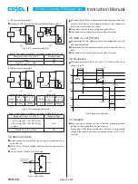
¡
Ripple and ripple noise are measured, as shown in the Fig.2.6, by
connecting Co and JEITA attachment.
3 Function
3.1 Overcurrent protection (OCP) and Low
voltage protection (LVP)
¡
OCP and LVP circuits is built-in. LVP will trigger after 200ms typ
delay when OCP activates and output voltage drops down 90%
max (SFS20 : 95% max) of the rated output voltage.
¡
When LVP is activated, ALM signal will becomes low impedance.
¡
Recovery from the protection is accomplished by applying 5VDC
or less input for at least 1 second, or toggling remote ON / OFF
signal for at least 1 second.
3.2 Overvoltage protection (OVP)
¡
The overvoltage protection circuit is built-in and comes into effect
at 120% to 140% (SFS20 : 115% to 145%) of the rated output volt-
age. When the load factor is less than 50%, output voltage may
be increased more than maximum voltage by the failure mode.
¡
Normal or abnormal operation of the unit can be monitored by us-
ing the ALM pin. When OVP is activated, ALM signal will become
low level.
¡
The DC input should be shut down if overvoltage protection is in
operation.
¡
Please note that devices inside the power supply might fail when
voltage more than rated output voltage is applied to output pin of
the power supply. This could happen when the customer tests the
overvoltage performance of the unit.
3.3 Remote ON / OFF (RC pin)
¡
Remote ON / OFF circuits is built-in on input side.
¡
When remote ON / OFF function is not use, please open-circuit
between RC and +Vin or short-circuit between RC and -Vin.
¡
Recovery from the protection is accomplished by applying 5VDC
or less input for at least 1 second, or toggling remote ON / OFF
signal for at least 1 second.
DC-DC Converters PCB Mount Type
Instruction Manual
Fig.2.3 Example of conducted noise (SFS30483R3)
Fig.2.4 Reverse input voltage protection
Fig.2.5 Connection for pulse load
Frequency [Hz]
200k 300k
500k
150k
1M
2M
3M
5M
10M
20M
30M
100
30
40
50
60
70
80
90
Level [d
B
V]
CISPR22-A (Ave.)
CISPR22-A (QP)
+Vin
-Vin
DC
Input
+Vout
Co
-Vout
Pulse
load
DC
Input
+Vin
-Vin
Fuse
+Vout
-Vout
SFS30483R3
1 H
1 F
Vin=48V
Io=9A
Temp=25
C
Load
Fig.2.6 Measuring method of ripple and ripple noise
+Vout
-Vout
Load
25mm
DC
Input
+Vin
-Vin
Co
Oscilloscope
R
C
Bw:100MHz
1. 5m 50
W
Coaxial Cable
JEITA attachment
R =50
W
C =4700pF or 10000pF
1.2 - 5Vout : Co=22 F
10 - 15Vout : Co=0.1 F
SFS/SFCS-21
June 26, 2020


