Respond 19 Operators Manual (EUA), IFU105, Rev. G, DCO#: 340 Effective 01/25/2021
Page
1
of
152
English
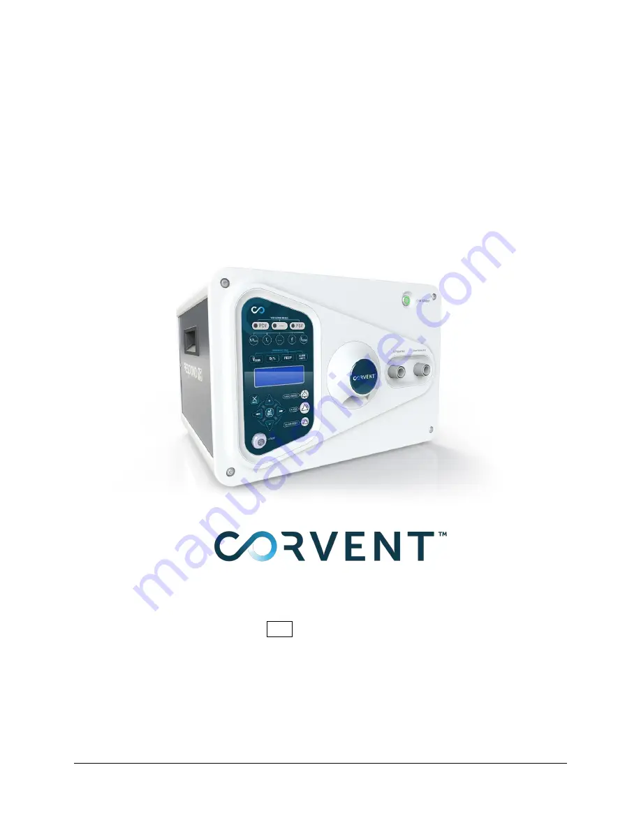
The RESPOND 19 Ventilator
User Manual
REF 3461-03-9000
Page 1: ...Respond 19 Operators Manual EUA IFU105 Rev G DCO 340 Effective 01 25 2021 Page 1 of 152 English The RESPOND 19 Ventilator User Manual REF 3461 03 9000 ...
Page 2: ...law to Emergency Use Only per the FDA Emergency Use Authorization The RESPOND 19 Ventilator is under US patent protection patent pending RESPOND 19 Ventilator is a Registered Trademark of the CorVent Medical Corporation Copyright 2020 by CorVent Medical Inc CorVent Medical Inc 315 West 36th St New York NY 10018 USA ...
Page 3: ...ms required for monitoring critically ill and mechanically ventilated patients Non Invasive Ventilation NIV may not be available in your geography Please contact CorVent Medical Support Section 9 0 for the availability status of this feature in your geography The RESPOND 19 Ventilator is NOT intended for multiplexing supporting more than one patient at one time DO NOT use the ventilator at an alti...
Page 4: ...y qualified personnel and an alternative means of ventilation is recommended whenever the ventilator is in use A UPS must be used with the Ventilator to provide up to 2 hours of backup power upon total loss of mains power supply When a UPS is connected the Ventilator will NOT indicate when the UPS has switched from mains supply to backup battery supply The user must rely upon the UPS alarms to und...
Page 5: ... environment and the unit Alarms The high priority and medium priority alarms have similar auditory indications These two alarm priorities are mainly differentiated by visual indications Red signals a high priority alarm and yellow signals a medium priority alarm Please refer to the Alarm section of this manual for additional alarm information PLEASE READ THIS MANUAL BEFORE OPERATING THE SYSTEM ...
Page 6: ...it HME Viral Filters and Flow Sensor to Ventilator and Patient 36 6 5 Powering the Ventilator On and Operational Verification 40 6 6 Selecting Ventilation Type 42 6 7 Connecting to Oxygen 44 6 8 Setting Parameters and Patient Ventilation 47 6 9 Shutting Down the Ventilator 67 6 10 Replacing the Patient Circuit HME Viral Filters 68 6 11 Possible Locations of Contamination 69 6 12 Suctioning 70 7 0 ...
Page 7: ...s High and Low Inspiratory Pressure Limits Disconnect High and Low Exhaled Tidal Volume Apnea and High Respiratory Rate These features constitute the basic functionality needed for the ventilator to provide a life supporting capacity The RESPOND 19 system design leverages known technology in ventilators The Ventilator supports patients by controlling the speed of a micro blower motor It is electri...
Page 8: ...ock the gas intake port or emergency intake port thereby interfering with patient ventilation Do NOT block the fan intake or otherwise cover or position the ventilator in a way that adversely affects its operation or performance For example positioning the ventilator next to a curtain that blocks the flow of cooling air can cause the ventilator to overheat and shut down resulting in patient injury...
Page 9: ...19 Ventilator The RESPOND 19 Ventilator is not intended to be operated by patients or laypersons Adults only The RESPOND 19 Ventilator has been designed for use on adult patients greater than 60 lb DO NOT use on neonatal infant or pediatric patients Alarm High Medium Priority The high priority and medium priority alarms have similar auditory indications These two alarm priorities are mainly differ...
Page 10: ...pply The UPS is not intended to be used to power your RESPOND 19 Ventilator but for backup power purposes in the event of an unexpected loss of power When a UPS is connected the Ventilator will NOT indicate when the UPS has switched from mains supply to backup battery supply The user must rely upon the UPS alarms to understand the status of their mains supply and backup battery life using the audi...
Page 11: ...d in the instructions for use as this can affect the performance of the ventilator that can consequently result in patient death or serious deterioration of health An alarm will not sound on the Ventilator if there is an interruption to the O2 supply If the supply is interrupted it could result in the FiO2 being lower than the amount set on the unit down to 21 Appropriate patient monitoring should...
Page 12: ...sk of fire use the ventilator in well ventilated areas To reduce patient risk of oxygen toxicity keep free flowing oxygen away from air inlet of ventilator Interdependent Functions Due to the design of the ventilator see Appendix 1 Principles of Operation the patient settings are interdependent The Pressure Target Inspiratory Time and Respiratory Rate controls are all calibrated controls however t...
Page 13: ...reathing system filter frequently for increased resistance and blockage to ensure the delivery of the therapeutic pressure Other Gases DO NOT use the ventilator with other gases other than room air and wall oxygen Device Startup Make sure the device is working properly at startup by following the instructions in section 6 Contact CorVent if the listed testing does not work Biocompatibility All ven...
Page 14: ...or performance use only accessories compatible with the ventilator DO NOT place the Flow Sensor in contact with the patient The Flow Sensor is heated to prevent condensation and may exceed 30 C depending on ambient temperature The maximum temperature rise is less than 5 C above ambient temperature Ensure the Flow Sensor is not in direct contact with the patients skin The system will alarm if the L...
Page 15: ...nect the patient from it and immediately start ventilation with alternative device The defective ventilator must be removed from clinical use and sent back to CorVent if possible If any unexplained changes in the performance of the device are noticed if it is making unusual or harsh sounds or if the device or power supply are dropped or mishandled discontinue use and contact CorVent support Power ...
Page 16: ...cur in a particular installation Harmful interference to other devices can be determined by turning this equipment on and off Try to correct the interference using one or more of the following Reorient or relocate the receiving device Increase the separation between the equipment Connect the equipment to an outlet on a different circuit from that to which the other device s are connected Consult y...
Page 17: ...Deg C to 30Deg C Using the ventilator outside of this temperature range or above this altitude can compromise the ventilator performance which consequently can result in degradation of the health of the patient The Ventilator has only been tested at sea level and degradations in performance may occur at higher altitudes Condensation may damage the device If the device has been exposed to either ve...
Page 18: ...hthalates or natural rubber latex which may cause allergic reactions Electric Shock To reduce the risk of electric shock from liquid entering the device DO NOT put a container filled with a liquid on or near the ventilator To avoid the risk of electric shock this equipment must be connected to a supply main with a protective earth EM Interference The RESPOND 19 Ventilator may cause radio interfere...
Page 19: ...lth Helium Gas Mixtures The ventilator shall not be used with inlet gases which are not specified for use e g helium or mixtures with helium Such use might cause the ventilator to not function correctly causing patient death or serious deterioration of health Caution indicates the possibility of damage to the device System Characteristic Caution Condensation Condensation may damage the device If t...
Page 20: ...aults are the same for each RESPOND 19 ventilator are un editable and reset to Default upon power cycling See the Limited Warranty section of this manual for information on warranty coverage 3 2 Contraindications The RESPOND 19 Ventilator is contraindicated in the following situations Active Pneumothorax Neonatal Infant and Pediatric patients Use of this device may be contraindicated depending on ...
Page 21: ... for immunity to electrostatic discharge Temperature limitation to which the medical device can be safely exposed Humidity limitation to which the medical device can be safely exposed Atmospheric pressure limitation to which the medical device can be safely exposed TYPE BF APPLIED PART The Flow Sensor flow sensor cable Inhalation Exhalation filters HME and patient circuit are the patient applied p...
Page 22: ...Alternating Current Direct Current Mandatory action sign Operators manual must be read prior to use Reference Operators manual Explosion Risk Oxygen rich environment Fire Risk Oxygen rich environment Keep away from flame No Latex present in system Electric Shock Hazard Waste Electrical and Electronic Equipment Directive WEEE The symbol indicates that the product should not be discarded as unsorted...
Page 23: ...ian prescription Do not use if package or device is damaged Alarm Pause Pause the audio indication of an alarm for a short period of time Alarm Silence Reset an alarm if it continues to annunciate even though the condition causing the alarm is no longer present Altitude Limitation Keep out of Sunlight This way up Fragile Handle with care Stacking weight limitation Stacking limitation of the same b...
Page 24: ...Mean Airway Pressure cmH2O MV Minute Ventilation L min NIV Non Invasive Ventilation O2 Percent Oxygen PCV Pressure Control Ventilation PEEP Positive End Expiratory Pressure PF Peak Flow Rate L min PI Inspiratory Pressure Target POST Power On Self Test PP Peak Pressure cmH2O PSUPP Pressure Support Target PTarget Pressure Target PSV Pressure Support Ventilation Qi Inspiratory Flow Qaw Flow at Patien...
Page 25: ...separately Single Use RESPOND 19 Patient Circuit Single Use Heat Moisture Exchanger HME Single Use Bacterial Viral Filters Single Use Flow Sensor Reusable Flow Sensor Cable Operators Manual Quick Start Guide Quick User Interface Reference Guide FDA disclosure documents o Fact Sheet For Healthcare Providers March 24 2020 o Fact Sheet for Patients March 24 2020 The system is provided in a non steril...
Page 26: ...Respond 19 Operators Manual EUA IFU105 Rev G DCO 340 Effective 01 25 2021 Page 26 of 152 5 2 System Overview and Key Performance Specifications 1 2 3 4 5 6 7 8 9 12 13 14 16 10 15 11 ...
Page 27: ...Respond 19 Operators Manual EUA IFU105 Rev G DCO 340 Effective 01 25 2021 Page 27 of 152 19 20 17 18 21 22 23 24 ...
Page 28: ...From Patient Inlet Port Standard 22mm 8 To Patient Outlet Port Standard 22mm 9 Ventilator Enclosure 10 Ventilator Air Inlet Port 11 Ventilator Label 12 Oxygen Flow Rate Label 0 15 L min Low Flow Oxygen 13 Ventilator Carrying Handles 14 Covered Power On Off Switch Use per Section 6 5 15 Blended Oxygen Inlet Connection Connect during setup per Section 6 4 Cap when not in use 16 Power Supply Connect ...
Page 29: ...omatically Set User over rideable High Respiratory Rate Limit 20 80 BPM Automatically Set User over rideable Apnea Hypoventilation Limit 10 40 secs Automatically Set User over rideable Disconnect Limit 10 90 of delivered Tidal Volume Low Exhaled Tidal Volume Limit 50 1000 mL General Specifications Flow Rate Max 120 L min BTPS Oxygen Supply flow meter Blender Up to 15 L min Circuit Compliance 2 ml ...
Page 30: ...61 03 9000 This Kit Includes 1x 3461 03 1000 1x 3461 03 9120 1x 3461 03 9200 1x 3461 03 9300 1x 3461 03 9400 RESPOND 19 Base Ventilator Kit 3461 03 9110 This Kit Includes 1x 3461 03 1000 1x 3461 03 9120 RESPOND 19 Ventilator 3461 03 1000 Complete Patient Circuit Kit 3461 03 9200 This Kit Includes 1x 3461 03 9210 1x 3461 03 9220 2x 3461 03 9230 1x 3461 03 9240 Patient Circuit 3461 03 9210 HME 3461 ...
Page 31: ...01 25 2021 Page 31 of 152 Part Description Part Picture of Part Inhalation Exhalation Filter 3461 03 9230 Flow Sensor 3461 03 9240 Filter Port Adapter 3461 03 9280 Flow Sensor Cable 3461 03 9300 Power Supply 3461 03 9400 UPS 3461 03 9500 Oxygen Monitor 3461 03 9600 ...
Page 32: ...Picture of Part Literature Kit 3461 03 9120 Operators Manual Quick Start Guide Quick User Interface Reference EUA Fact Sheet for Healthcare Providers EUA Fact Sheet for Patients The RESPOND 19 Ventilator must be purchased as part of the Complete Ventilator Kit 3461 03 9000 or the Base Ventilator Kit 3461 03 9110 ...
Page 33: ...heated to prevent condensation rainout and may exceed 30 C depending on ambient temperature The maximum temperature rise is less than 5 C above ambient temperature Ensure the Flow Sensor is not in direct contact with the patients skin Caution DO NOT place ventilator directly onto carpet fabric or other flammable materials 6 2 Supplying Power Warnings Upon loss of power the device will alarm and st...
Page 34: ...ge To connect the ventilator to power ensure the system power switch is in the OFF position Align the power connection with the Locking power connection on the rear of the unit Press firmly until an auditory click is heard this ensures a locked connection lowering the risk of unintended power cable exertion Once the ventilator locking power connection is attached the system can be plugged into to ...
Page 35: ...backup battery with four beeps every 30 seconds with battery symbol on UPS LCD a Low battery Condition battery run time low with continuous beeping and symbol on UPS LCD as well as overload alarms and the depletion of the UPS backup battery When the UPS battery is completely depleted the Ventilator Total Loss of Power alarm will annunciate for 2 minutes Do NOT plug any other device into the UPS to...
Page 36: ... Sensor to Ventilator and Patient Warnings Inspect the breathing circuit and HME for wear or damage DO NOT use if damaged Only replace with CorVent supplied Breathing Circuit or HME DO NOT pull or stretch the tubing this could result in circuit leaks The RESPOND 19 Ventilator has not been tested for safety during defibrillation 6 4 1 Connecting the Viral Inhalation and Viral Exhalation Filters War...
Page 37: ...n alarm state can occur The filters have unidirectional connections and are the same for both the inhalation limb and the exhalation limb Each patient circuit limb can be connected to either ventilator port upon setting up the ventilator however the limbs should never be switched once patient ventilation has begun Ensure complete connection to both the ventilator ports and the distal circuit conne...
Page 38: ...system will Alarm for Flow Sensor Reversed if the Flow Sensor is placed incorrectly Ensure the Flow Sensor is placed in the proper orientation as indicated in the images below 6 4 4 Connecting the Flow Sensor Cable to Flow Sensor and Ventilator Use ONLY CorVent provided Flow Sensor components After assembly apply light pulling pressure at Flow Sensor cable connections to verify their correct assem...
Page 39: ...s per standard of care 6 4 6 Connecting to Patient Using the assembled respiratory circuit press the open end of the HME into the standard ETT 22mm adapter until securely connected as per standard of care Verify functionality visually and with the system functionality Alarms will sound if improperly connected The HME must be between the patient and the Flow sensor as shown below ...
Page 40: ...D s light up that the buzzer beeps once and that the Speaker beeps three times The following screen will be displayed upon POST pass A l l P O S T t e s t s h a v e s u c c e s s f u l l y p a s s e d After POST passes the user is asked if they are Ventilating a new patient or an old patient in order for the Ventilator to log this event The following screen will be displayed V e n t i l a t i n g ...
Page 41: ...i f e l e f t X X X D a y s If needed a secondary screen can be scrolled to with the Left and Right Arrows that displays relevant Ventilator information C O R V E N T M E D I C A L S W R E V X X X X X X X 2 Run Mode The ventilator delivers breaths in this mode at the prescribed breath settings but will also deliver assist breaths if patient triggers are detected Depress the Standby key for 1 secon...
Page 42: ...rigger Sensitivity is pressed The currently active type of ventilation is displayed as well The user can use Cancel x at any time to revert and leave the adjustment screen They also may use the scroll Left and Right Arrows in order to show the trigger sensitivity setting screen V e n t i l a t i o n t y p e N I V A c t i v e P R E S S f o r I n v a s i v e P R E S S C A N C E L t o E X I T or V e ...
Page 43: ... S C A N C E L T O E X I T or P R E S S S E L t o C O N F I R M C h a n g e N I V t o I n v a s i v e P R E S S C A N C E L T O E X I T When the system is in NIV the center Breath type LED is lit solid green When the button is pressed the screen shown below is displayed on the following LCD screen N I V N O N I N V A S I V E V e n t i l a t i o n A C T I V E C h a n g e i n S t a n d b y Center LE...
Page 44: ...it could result in the FiO2 being lower than the amount set on the unit down to 21 Appropriate patient monitoring should be used as medically indicated such as an alarming pulse oximeter and the required external alarming Oxygen monitor There is a risk of fire if O2 buildup within the unit is 25 or higher The system is designed to limit the build up of oxygen within the ventilator to less than 25 ...
Page 45: ...red MV may be affected by the addition of Oxygen Flow and may require the system to stabilize at the initially recommended Oxygen flow rate and then be altered once the new MV has stabilized 6 7 3 External Oxygen Monitor An external Oxygen monitor 3461 03 9600 is recommended for use with the RESPOND 19 Ventilator to provide the user with direct feedback that the delivered Oxygen percent is within ...
Page 46: ...ommended that the batteries on the external Oxygen monitor 1 200 hour battery life be replaced between each patient to ensure that the system can provide continuous monitoring for the duration of Ventilation Refer to the Oxygen monitor Operators manual IFU111 Rev A for complete instructions for use ...
Page 47: ...may set 1 Pressure Support Target PSUPP 2 Exhalation Sensitivity ESENS In SIMV PCV PSV the user may set 1 Inspiratory Pressure Target PI 2 Inspiratory Time TI 3 Breath Rate f 4 Pressure Support Target PSUPP 5 Exhalation Sensitivity ESENS The user may always set Common Settings 1 Trigger Sensitivity V SENS 2 O2 Based on Minute Ventilation and set externally by wall O2 flow 3 PEEP 4 Alarm settings a...
Page 48: ...ilator setting adjustments 6 8 2 Monitored and Displayed Parameters The Current Settings screen displayed corresponds to active breath type and Monitored Parameters common across breath types will be displayed to the user during Run mode The two screens displayed are shown below and are referred to as the Main Menu This is a manual cycling of displays The user can utilize the Left and Right arrow ...
Page 49: ...Value Display S I M V P C V P S V P I X X T I X X s B P M X X P S X X c m H 2 O E S X X p c t P E E P X X T S X X L m i n 1 TI Inspiratory Time TI 2 BPM Breath Rate f 3 PS Pressure Support Target PSUPP 4 ES Exhalation Sensitivity ESENS 5 PEEP Peak End Expiratory Pressure PEEP 6 TS Trigger Sensitivity V SENS NIV Settings Value Display When in Non Invasive the Settings value display for each Ventila...
Page 50: ...2O 7 PF Peak Flow L min 8 MAP Mean Airway Pressure cmH2O 9 I E Inspiratory Expiratory Ratio 6 8 3 Changing Ventilator Mode The RESPOND 19 Ventilator defaults to Pressure Control Ventilation PCV upon system startup The Ventilator requires that a Ventilation mode to always be active i e the user cannot disable all modes The user may change Ventilation modes in either Run Mode or Standby Mode To ensu...
Page 51: ... a b l e S I M V P C V P S V P R E S S C A N C E L T O E X I T PSV PCV P R E S S U R E C O N T R O L P R E S S S E L t o e n a b l e S I M V P C V P S V P R E S S C A N C E L T O E X I T PSV P R E S S U R E S U P P O R T P R E S S C A N C E L T O E X I T SIMV PCV PSV PCV S I M V P C V P S V P R E S S f o r P C V o n l y P R E S S f o r P S V o n l y P R E S S C A N C E L T O E X I T PSV S I M V P ...
Page 52: ... S U P P O R T N I V P R E S S U R E C O N T R O L When a ventilation breath type screen is shown the user is capable of exiting to the Main Menu of settings and monitored values at any time Note This can be accomplished with the Cancel X key or by waiting 10 seconds for the screen to timeout The user is required to press a discrete key key defined in the LCD screen display table shown above i e k...
Page 53: ... T I N G C O N F I R M E D If the Cancel X key is used or no adjustments are made after 10 seconds the system will cancel the adjustment and return to its home screen For keys with multiple settings i e the PI PSUPP key or Alarm Limits key after the user presses the key and the initial setting is displayed on the LCD depress the same key again or use the scroll arrows left right to cycle through t...
Page 54: ...at they are available for edit Backlit LED keys are used to elucidate relevant settings for user A PCV B PSV C SIMV PCV PSV If a key is pressed that is not active then the following screen will annunciate S E T T I N G N O T A V A I L A B L E i n t h i s b r e a t h t y p e Common settings are always available to the user 6 8 5 Patient Ventilation Settings Setting details shown in example display ...
Page 55: ...ted at the start of the next inspiration Active Mode Only active in PCV and SIMV PCV PSV modes LCD Display P C V P I X X c m H 2 O R a n g e 5 t o X X c m H 2 O P E E P X X c m H 2 O V i V e X X X X X X m L 2 Inspiratory Time TI The Inspiratory Time setting details are as follows Units sec Breath Types PCV only Range 0 4 3 0 Increments 0 1 total of 27 possible settings Default 0 8 Accuracy 0 1 1 o...
Page 56: ...t i o X X X X M i n V e n t X X X L m i n 4 Pressure Support Target PSUPP The Inspiratory Pressure Target setting details are as follows Units cmH2O Breath Types PSV only Range PSUPP can range from 0 to 40 cmH2O PEEP Thus PTARGET PSUPP PEEP having a maximum of 40 cmH2O Therefore the maximum PSUPP the user can set PSUPPMAX 40 PEEP Increments 1 total of 41 possible settings Default 10 Accuracy 2 4 o...
Page 57: ...Units of peak flow Breath Types PSV only Range 5 80 Increments 5 16 settings Default 25 Accuracy 10 of peak flow or 5L min whichever is greater Setting Change Implemented at the start of the next inspiration Active Mode Only active in PCV and SIMV PCV PSV modes LCD Display P S V E X H S E N S X X R a n g e 5 t o 8 0 M e a s V i V e X X X X X X m l P e a k F l o w X X X L m i n ...
Page 58: ...tivity setting details are as follows Units L min Breath Types PCV only Range 0 5 to 20 Increments 0 5 L min increments between 0 5 and 5Lpm 1 Lpm thereafter 25 settings Default 2 Accuracy 1 L min 5 of setting of delivered set pressure Setting Change Implemented immediately Active Mode Always active in Invasive When a patient takes an assist breath the corresponding LED to Trigger Sensitivity will...
Page 59: ...on LCD Display N I V T r i g S e n X X R a n g e 1 t o 1 0 P e a k F l o w X X X L m i n M e a s B P M X X b p m 3 O2 The O2 setting details are as follows Note This is a calculation done for the user and does not directly alter the delivered Oxygen The user is required to externally set the wall O2 flow to achieve the desired O2 The O2 can only be set while in Run Mode in order for MV to update t...
Page 60: ... e M i n u t e V e n t i l a t i o n i s M e a s u r e d 4 PEEP The PEEP setting details are as follows Units cmH2O Breath Types PCV PSV SIMV PCV PSV Range 0 to 20 Therefore the Maximum PEEP MIN 40 PI 40 PSUPP 20 Increments 1 total of 21 possible settings Default 5 Accuracy 2 4 of setting cmH2O Setting Change Implemented at the start of the next expiration Active Mode Always active LCD Display P E...
Page 61: ...just the corresponding alarm settings Confirm alarm limit adjustment with the Enter SEL key Caution The alarm pre sets Defaults are the same for each RESPOND 19 ventilator are un editable and reset to Default upon power cycling Note Alarm limits are always active while in Run Mode all breath types 1 High Exhaled Tidal Volume Limit The High Exhaled Tidal Volume alarm is annunciated based on the exh...
Page 62: ...or two breaths after a PEEP PI or PSUPP change LCD Display L o w E x h T V X X X m l R a n g e 2 5 t o 1 0 0 0 m l M e a s V e X X X m l 3 Apnea Limit automatically set user adjustable The Apnea alarm is annunciated when the time since the initiation of the last inspiration is greater than set apnea interval The user may adjust this Apnea setting The Apnea Limit setting shall have the following Un...
Page 63: ...ext inspiration LCD Display H i R e s p R a t e X X b p m R a n g e 2 0 t o 8 0 b p m S e t H R R X X b p m M e a s B P M X X b p m 5 Disconnect Limit The Disconnect Limit is annunciated based upon the Inhaled and Exhaled tidal volume percent difference For example Vi Ve 400 350 the percent difference would be Vi Ve Vi 400 350 400 12 5 In order to get a disconnect the difference must be greater th...
Page 64: ...P PI 5 20 50 This will be overridden by the user set value PSV and SIMV Support Breaths HP MIN MAX PEEP PSUPP 5 20 50 This will be overridden by the user set value Setting Change Shall be immediately implemented after a Pressure Target setting update in PSV PCV and SIMV The HP Limit can not be set less than the LP Limit The HP limit will be immediately implemented after a HP limit change For more ...
Page 65: ...Units cmH2O Breath Types PCV PSV SIMV PCV PSV Range 1 to 35 Increments 1 35 settings Default 1 If PCV MIN MAX PEEP PI 5 1 35 This will be overridden by the user set value 2 If PSV MIN MAX PEEP PSUPP 5 1 35 This will be overridden by the user set value 3 LP limit will switch between breaths in SIMV Setting Change Shall be implemented at the start of the next inspiration LCD Display R e l a t i v e ...
Page 66: ... in exhalation LCD Display H i g h P E E P X X c m H 2 O R a n g e 5 t o 2 5 c m H 2 O P E E P X X C u r r H P E E P X X P I X X P S U P P X X 9 Low PEEP Limit automatically set user adjustable The Low PEEP setting shall have the following Units cmH2O Breath Types PCV PSV SIMV PCV PSV Range 1 to 15 Increments 1 17 settings Default Low PEEP MIN MAX PEEP 3 1 15 Accuracy 2 4 of setting cmH2O Setting ...
Page 67: ...rm given that the user is present If the alarm pause key is not depressed twice in rapid succession the Ventilation Stop request alarm will clear and the system will continue to ventilate R E Q U E S T V E N T S T O P P R E S S A U D I O P A U S E T W I C E t o S T O P V E N T I L A T I O N To Power down the unit turn off the Oxygen supply BEFORE turning off the power switch to the unit This will ...
Page 68: ...n efficacy due to build up of copious secretions This can be indicated by alarm states of high inspiratory pressure or by external monitoring Otherwise it is recommended to minimize changing frequency to minimize provider exposure to aerosolized pathogens when opening the patient circuit To replace filters same filter for inhalation and exhalation ensure the patient is in a stable breathing patter...
Page 69: ...dditional safety and preventing contamination of the environment with exhaled gas Reversing the orientation of the exhalation filter during use will only result in the environment being contaminated if the HMEF is not filtering correctly or is not present Care must be taken not to reverse orientation and to ensure all filters are in place during operation If disconnecting make note of the position...
Page 70: ...m may be annunciated Breath delivery will continue during suctioning If a disconnect alarm is annunciated triggering will be disabled for 4 seconds and will reset automatically In order to begin suction set the O2 to 100 for a few minutes before initiating suctioning if in the medical opinion of the physician this is necessary Any Ventilation modes and settings can be used for closed suctioning If...
Page 71: ...ator sounds when a High or Medium priority alarm condition occurs which can include device inoperable conditions and patient ventilation mismatch A complete list of alarms is listed below WARNING The high priority and medium priority alarms have similar auditory indications These two alarm priorities are mainly differentiated by their visual indicator of LED color Red High Yellow Medium and freque...
Page 72: ...les Speaker Sound File Decibel Level Interburst Interval High Priority Red Run 2 0 Hz 50 B B B space B B C4 A4 F4 A4 F4 VEN TI LA TI ON VEN TI LATE A LARM 50 85 dBA 4 5 s Medium Priority Yellow Run 0 7 Hz 50 B B B C4 A4 F4 VEN TI LATE RISE AND FALL 50 85 dBA 6 10 s Normal Green Run Constant on 100 on None None NA NA Low Priority POST Failure Yellow Standby Constant on 100 on None None NA NA Normal...
Page 73: ...ED will be cleared in the event of a mode transition There are two mode transitions Standby to Run Mode and Run Mode to Standby Mode While the AUDIO PAUSED is active the corresponding LED will indicate as a solid yellow LED on Resetting Alarm Alarm Reset Key The ventilator will reset resolve the active alarm if the Alarm Reset key is held for 2 seconds continuously Note Upon entry to Standby mode ...
Page 74: ...ndby mode when the AUDIO PAUSED Key is pressed twice in quick succession The alarm shall clear automatically in 5 seconds if the AUDIO PAUSED Key is not pressed twice in quick succession and the ventilator will continue in Run Mode Note this will force two actions to by the user to stop ventilating System Inoperable The SYSTEM INOPERABLE alarm occurs in Run Mode when the Ventilator has failed BIOT...
Page 75: ...ed when the Flow Sensor ceases to output data the rate is too slow or data is missing from the Flow Sensor data received The following text strings are displayed when a FLOW SENSOR NOT CONNECTED Alarm is annunciated F L O W S E N S N O T C O N N E C C h e c k s e n s c o n n e c t e d C h e c k e l e c t c o n n a t s e n s o r a i r w a y The FLOW SENSOR NOT CONNECTED Alarm will auto reset when t...
Page 76: ...te occlusion O C C L U S I O N A L A R M C h e c k f o r k i n k i n g C h e c k f o r b l o c k e d f i l t e r o r w a t e r The OCCLUSION alarm will auto reset when the alarm condition is no longer present for a new breath period Low Inspiratory Pressure LP The LOW INSP PRESSURE alarm will annunciate when the monitored pressure never rises above LOW INSP PRESSURE setting during inspiration for ...
Page 77: ...led tidal volume limit for 3 out of 4 consecutive breaths High Respiratory Rate The HIGH RESP RATE alarm will annunciate when the measured breath rate is higher than the set High Respiratory Rate breath rate limit H I G H R E S P R A T E C h e c k f o r c u f f l e a k C h e c k t r i g s e n s i v i t y M e a s B P M X X b p m When a HIGH RESP RATE alarm is annunciated the measured Breath rate sh...
Page 78: ...larm is annunciated H I G H E X H T I D A L V O L C h e c k i n s p E x p l i m b C h e c k P r e s s S e t t i n g C h e c k H i g h V e l i m i t The HIGH EXHALED TIDAL VOL alarm will auto reset when the exhaled tidal volume is less than the user set high exhaled tidal volume limit for 3 out of 4 consecutive breaths High PEEP The HIGH PEEP alarm is annunciated when the measured PEEP is higher th...
Page 79: ...reset the alarm when the measured PEEP is greater than the alarm setting for 5 breaths Flow Sensor Reversed The FLOW SENSOR REVERSED alarm is annunciated when the Flow Sensor is inserted in the wrong direction Note We will only need this alarm because user can reverse the direction of the Flow Sensor The following text strings are displayed when a FLOW SENSOR REVERSED Alarm is annunciated F L O W ...
Page 80: ...reset system to clear the alarm Replace Ventilator if keyboard failure persists Life Exceeded The LIFE EXCEEDED alarm occurs in Run Mode when the Ventilator has surpassed its indicated life L I F E E X C E E D E D 3 6 5 3 6 5 D a y s o f u s e R E P L A C E V E N T I L A T O R The LIFE EXCEEDED alarm annunciates only once while in Run Mode The LIFE EXCEEDED alarm requires the user to hold the Alar...
Page 81: ...ycle of troubleshooting as outlined in alarm table to ensure patient safety and ventilation efficacy is maintained 5 Note the alarm and refer to the alarm descriptions in this section to determine the cause of the alarm and the appropriate action 7 5 External Power Failure WARNING Upon loss of power the device will alarm and stop working There is NO internal backup battery There should be continuo...
Page 82: ...n Alarm Description User Actions Ranking REQUEST VENTILATION STOP Medium priority alarm Upon request of entry to Standby Mode from Run Mode the system will declare an alarm alerting the user that the device has been requested to stop ventilation The user will be required to press the AUDIO PAUSED key twice to enter Standby Mode and reset the alarm If pressed in error the user may wait 5 seconds be...
Page 83: ...cated because ventilator breathing circuit pressure reached HIGH PRESSURE setting Inspiration phase ends and exhalation valve opens to prevent excessive pressure Action Ventilator continues ventilation at user set breath rate Triggering is disabled for 4 seconds when in PSV Auto reset When circuit pressure is less than alarm setting for 5 breaths Cannot be silenced if alarm condition persists Chec...
Page 84: ...bove normal difference between inspiratory and expiratory pressure transducers This could be a partial or complete occlusion Action Ventilator continues ventilation at user set breath rate Triggering is disabled for 4 seconds when in PSV Auto reset When the ventilator no longer detects an occlusion on the next breath Check patient Check ventilator breathing circuit and inspiratory and expiratory f...
Page 85: ...alue at least equals the alarm setting for 3 out 4 consecutive breaths Check patient Consider appropriate exhaled tidal volume limit Consider increasing pressure 8 HI RESP RATE user adjustable Medium priority alarm Monitored respiratory rate higher than HIGH RATE setting Action Ventilator continues ventilation at user set breath rate Triggering is disabled for 4 seconds when in PSV Auto reset When...
Page 86: ...onsider decreasing pressure 11 HIGH PEEP user adjustable Medium priority alarm High PEEP limit is automatically set to 3 cmH2O higher than the PEEP Setting the user may override The monitored PEEP pressure rises above HIGH PEEP setting during exhalation for 3 out of 4 breaths The user may adjust this HIGH PEEP setting Action Ventilator continues ventilation at user set breath rate Triggering is di...
Page 87: ...on of exhalation port FLOW SENSOR REVERSED Medium priority alarm The flow sensor was placed in the wrong orientation and should be reversed Action Ventilator continues ventilation at user set breath rate The sensor reading is multiplied by 1 0 and triggering is enabled until the flow sensor is reversed Auto reset When console see the flow sensor in the correct direction Check patient Reverse conne...
Page 88: ... the passing of the indicated operational lifetime in no way represents a risk to the patient at present it simply means that the ventilator has surpassed the indicated allowed lifetime under the authorized labeling of the ventilator Check Patient Reset Alarm Replace Ventilator after patient support complete 16 TOTAL LOSS OF POWER HIGH priority alarm This is a hardware alarm Power cycle ventilator...
Page 89: ...nal UPS for more details Must be set to alarm when battery has 10 mins left of battery life at system load Find alternative MAINS to reinstate power input or alternative method of backup patient ventilation support NA LOSS OF MAINS SWITCHOVER TO INTERNAL BATTERY Medium priority alarm This is an alarm integrated into external hardware Refer to external UPS for more details This is a hardware alarm ...
Page 90: ...ice and replace unit Ventilator airflow does not begin Potential hardware or software error Check power to the system plug outlet Depress On Standby button ensure green light is solid on power button and LCD displays settings of ventilation If occurs 3 times contact CorVent Service and replace unit Device display is erratic Potential hardware or software error Potential Interference from external ...
Page 91: ... POST or BIOT Failure Internal Electronic Self Test Failure Cycle power to reset system If occurs 3 times contact CorVent Service and replace unit Screen Blank or Solid White Boxes show up Blocking rows Internal Communication Error Momentarily press the Run Standby button quickly 0 2 sec This will reset the LCD and membrane panel Power cycle unit to reset system if problem persists If occurs 3 tim...
Page 92: ...ice to gain access to a port The device also does not contain any wireless devices There are no known unresolved software anomalies and workarounds There are no known unresolved software anomalies that can lead to the compromise of sensitive information or that can affect communication security as there is no method for interface with external systems 7 9 System Checkout Procedure Between each pat...
Page 93: ...e correct operation of the system may be derived For more details on system architecture refer to Appendix I If required to independently verify the system output connect the system to a standard test lung ideally instrumented to ensure that the ventilator is functioning properly The SST takes less than one minute to complete when a user is fully prepared to run the test and can be canceled at any...
Page 94: ...ired by SST Qwye The user will be guided through the SST and requires the patient to block and unblock the patient wye in order for the test to properly run The screens for the SST are as follows the first test that will run is Compliance B l o c k P a t i e n t W y e f o r e n t i r e t y o f t e s t T e s t 1 o f 3 R e a d y P r e s s S S T R u n n i n g T e s t 1 o f 3 P i X X P e X X Q i X X Q...
Page 95: ... a d y P r e s s S S T R u n n i n g T e s t 2 o f 3 P i X X P e X X Q i X X Q a w X X E n s u r e W y e U n b l o c k e d The third and final test that will run is Resistance B l o c k P a t i e n t W y e f o r e n t i r e t y o f t e s t T e s t 3 o f 3 R e a d y P r e s s S S T R u n n i n g T e s t 3 o f 3 P i X X P e X X Q i X X Q a w X X E n s u r e W y e B l o c k e d ...
Page 96: ... L E D C X X m L c m H 2 O L e a k X X X m L m i n R i X X R e X X R h m e X X c m H 2 O L p s Note Where the follows the failed test parameter in the example shown above the system has found a leak failure Troubleshooting Information C Compliance Failure may mean an incorrect patient circuit is used CorVent only Leak Failure may mean a disconnect is present Ri Inspiratory Resistance Failure may m...
Page 97: ...operate in Run mode for 30 seconds 12 Confirm that measured peak inspiratory pressure PIP is within 4 cmH2O 4 of set pressure target PI PEEP 13 Confirm no alarms present Alarm Description Test Procedure REQUEST VENTILATION STOP Medium priority alarm Upon request of entry to Standby Mode from Run Mode the system will declare an alarm alerting the user that the device has been requested to stop vent...
Page 98: ...erting the user that the system has a technical fault requiring power cycle The system will immediately stop Ventilation due to potential risk to the patient Action Ventilator must be power cycled Reset Can only be reset by power cycle and subsequent successful POST pass and BIOT monitoring demonstrating system operation within expected limits Confirm system passes POST and allows system to enter ...
Page 99: ...th rate Triggering is disabled for 4 seconds Auto reset When circuit pressure is less than alarm setting for 5 breaths Cannot be silenced if alarm condition persists 1 While in Run Mode Press Down sharply on the connected Test Lung at the end of inspiration for more than 2 breaths in a row This will force the air to exit the lung at a high pressure 2 Confirm high pressure alarm is generated Confir...
Page 100: ...l difference between inspiratory and expiratory pressure transducers The same alarm will occur for a partial or complete occlusion Action Ventilator continues ventilation at user set breath rate Triggering is disabled for 4 seconds Auto reset When the ventilator no longer detects an occlusion on the next breath For Complete Occlusion 1 Occlude the inspiratory or expiratory limb of the patient circ...
Page 101: ...Disconnect the inspiratory patient circuit while in Run mode 2 Clear the Disconnect Alarm with Alarm Reset Hold for two seconds 3 Confirm low pressure alarm is generated 4 Reconnect inspiratory limb Confirm alarm is auto reset after 30 seconds LOW EXHALED TIDAL VOL user adjustable Medium priority alarm When the measured exhaled tidal volume is less than the user set for 3 out of 4 consecutive brea...
Page 102: ...ivity to 0 5 LPM 3 Squeeze or extend the patient circuit tubing to create patient triggers during exhalation 4 Confirm High respiratory rate is generated 5 Adjust High respiratory rate limit back to default 40 BPM Confirm alarm is auto reset after 30 seconds APNEA user adjustable Medium priority alarm When the measured breath interval is lower than that set apnea interval Action Ventilator switche...
Page 103: ...idal volume should now be greater than 550 ml 4 Confirm High exhaled tidal volume is generated 5 Set high exhaled tidal volume alarm to 1500 ml and return target pressure to default Confirm alarm is auto reset after 30 seconds High PEEP user adjustable Medium priority alarm High PEEP limit is automatically set to 5 cmH2O higher than the PEEP Setting the user may override Action Ventilator continue...
Page 104: ...valve at least equals the alarm setting for 3 out of 4 breaths 1 Use ALARM LIMITS key to adjust Low PEEP alarm to 10 cmH2O 2 Set PEEP to 0 cmH2O 3 Confirm Low PEEP alarm is generated 4 Reset PEEP to 10 cmH2O and Reset Low PEEP alarm to 5 cmH2O Confirm alarm is auto reset after 30 seconds FLOW SENSOR REVERSED Medium priority alarm The flow sensor was placed in the wrong orientation and should be re...
Page 105: ...monitoring should be used as medically indicated such as an alarming pulse oximeter Use external monitoring to manage oxygen delivery efficacy and safety TOTAL LOSS OF POWER This is a hardware alarm 1 Run the system for 5 minutes 2 While the ventilator is running in Run mode pull the power cord from the wall 3 Confirm alarm is generated 4 Plug Ventilator back in 5 Ensure Power ON OFF switch is in ...
Page 106: ... 5 Plug UPS back into mains Confirm alarm is reset upon plugging UPS back into mains LOSS OF MAINS SWITCHOVER TO INTERNAL BATTERY Medium priority alarm This is an alarm integrated into external hardware Refer to external UPS for more details This is a hardware alarm 1 Connect ventilator to external UPS and begin ventilation 2 Unplug UPS from mains supply 3 Ensure a switchover to battery alarm loss...
Page 107: ...during normal operation Wiping down the outside of the system is sufficient In the case of a single fault failure i e Filter is missing damaged torn refer to Section 6 11 for details on the gas pathways through the Ventilator that can become contaminated with body fluids or expired gases Clean system between each patient or after any spill testing has been performed for a maximum of 14 cleanings P...
Page 108: ...mination Maintenance No user serviceable parts inside the Ventilator DO NOT attempt to service the unit Disposal DO NOT attempt to reuse the ventilator after its functional lifetime Dispose of in accordance with local regulations after use Waste of electrical and electronic equipment must not be disposed as unsorted municipal waste It must be collected separately and must be disposed as per local ...
Page 109: ...nt Support Hotline at 1 833 770 VENT and or at support CorVentmedical com Refer to labeling on Ventilator for up to date contact information DO NOT attempt to service the unit To return RESPOND 19 Ventilator to manufacturer contact the support hotline for instructions on how and where to send the unit Any attempts to modify the hardware of this device will void all warranties and liabilities ...
Page 110: ...70 oC 29 158 oF Long Term Storage 2 months Temperature 15 25 oC 59 77 oF Storage Transport Relative Humidity 0 95 non condensing Storage Transport Atmospheric Pressure Range 510 1081 hPa Shelf Life Within required Storage Conditions 5 years Dimensions 45 7 cm x 30 5 x 30 5 18 x 12 x 12 Weight including power supply 9 1 kg 20 lbs Sound Pressure Level of Ventilator while operating 65 dBA Reference E...
Page 111: ...r Basic Safety and Essential Performance Collateral Standard Usability Requirements and Tests IEC 60601 1 8 2012 Medical Electrical Equipment Part 1 2 General Requirements for Basic Safety and Essential Performance Collateral Standard General requirements tests and guidance for alarm systems in medical electrical equipment and medical electrical systems IEC 60417 2002 Graphical Symbols for Use on ...
Page 112: ...ed Oxygen Rich Environment Not intended for use in Oxygen rich environment Achieved with external UPS Electrical Characteristic Specification External AC DC Power Supply Rating 120 240 VAC 60 Hz to 24 VDC 120 Watt Fuses No User replaceable fuses contact CorVent Service if system has electrical failure Backup Power Life For all delivered volumes 2 minutes of audio visual alarm annunciation upon mai...
Page 113: ...sing Hydrophobic Coated Glass Fibers B V Efficacy 99 99 at 0 3 microns Dead Space Volume 34 mL HMEF Materials Polypropylene housing Polyurethane Foam Hydrophobic Coated Glass Fibers B V Efficacy 99 99 at 0 3 microns Humidity Output 32mg H2O L Dead Space Volume 15 mL Rebreathing A one way valve is used to direct airflow out of the micro turbine blower minimizing the risk of rebreathing The dead vol...
Page 114: ... NA Maximum Working Pressure PWmax 0 40 cmH2O 2 4 of setting cmH2O Achieved by pressure generation NA Patient Settings PCV Default Breath Type Breath Rate f 3 70 bpm 1 bpm 20 bpm Inspiratory Time TI 0 4 3 0 sec 0 1 1 of setting sec 0 8 sec Inspiratory Pressure Target PI 5 40 cmH2O PEEP 2 4 of setting cmH2O 15 cmH2O Patient Settings PSV Pressure Support Target PSUPP 0 40 cmH2O PEEP 2 4 of setting c...
Page 115: ...rror and the second value is the Maximum linearity error The declared tolerances have been adjusted to encompass the measurement uncertainty which are declared in the technical description The maximum error of the Airway Pressure PAW at the end of the inspiratory phase in relation to the setting is the same as PI or PSUPP which are 2 4 of setting cmH2O Response Time of the Ventilator Worst case VB...
Page 116: ...ally The maximum static pressure that the blower can generate will lower with altitude therefore the settable PTarget will vary with altitude as shown in the table below PmaxBlower 50 cmH2O Patm 1 013 25 hPa PTarget PCV PI PEEP or PTarget PSV PSUPP PEEP Altitude m Indicated Maximum Pressure Target PTarget cmH2O Nominal Barometric Pressure hPa Max Blower Pressure PmaxBlower cmH2O 0 40 1013 25 50 0 ...
Page 117: ... sec 5 ms at 3 BPM 4 sec 5 ms at 15 BPM Low Exhaled Tidal Volume 50 1 000 mL 150 mL 20 sec 5 ms at 3 BPM 4 sec 5 ms at 15 BPM Apnea 10 40 sec Auto Set User Over rideable PCV SIMV 15 seconds PSV 40 sec 5 ms set to 40 sec High PEEP 5 25 cmH2O Auto Set User Over rideable 80 sec 5 ms at 3 BPM 16 sec 5 ms at 15 BPM Low PEEP 1 15 cmH2O Auto Set User Over rideable 80 sec 5 ms at 3 BPM 16 sec 5 ms at 15 B...
Page 118: ... L min 0 999 L min Breath Rate 1 1 BPM 0 99 BPM Inspiration Volume 10 ml 10 of reading 1 ml 0 9999 ml Expiration Volume 10 ml 10 of reading 1 ml 0 9999 ml Peak Pressure 2 cmH2O 4 of reading 0 1 cmH2O 0 99 cmH2O I E Ratio 20 ms of inspiratory time 0 1 99 1 1 99 Mean Airway Pressure 2 cmH2O 4 of reading 0 1 cmH2O 0 99 cmH2O PEEP 2 cmH2O 4 of reading 0 1 cmH2O 0 99 cmH2O Low Pressure 2 cmH2O 4 of rea...
Page 119: ...th pressure control Group 1b Note 1 A C PC Assist Control Ventilation with Pressure Control SIMV Group 2 Group 2b Note 1 SIMV PC PS Synchronized Intermittent mandatory Ventilation with Pressure Control and Pressure Support PSV CPAP Group 4 Group 4a CSV PS Continuous spontaneous ventilation with pressure support Group 4b CPAP Continuous positive airway pressure Table E 1 Typical examples of ventila...
Page 120: ...crease the separation between the equipment Connect the equipment to an outlet on a different circuit from that to which the other device s are connected Consult your authorized dealer for help ELECTROMAGNETIC COMPATIBILITY EMC TABLES FOR RF EMISSIONS Guidance and Manufacturer s Declaration Electromagnetic Emissions The Respond 19 Model 3461 03 9001 is intended for use in the electromagnetic envir...
Page 121: ...ironment Surge IEC 61000 4 5 AC Mains Line to Ground 0 5kV 1kV and 2kV AC Mains Line to Line 0 5kV and 1kV AC Mains Line to Ground 0 5kV 1kV and 2kV AC Mains Line to Line 0 5kV and 1kV Mains power quality should be that of a typical commercial or hospital environment Voltage dips short interruptions and voltage variations on power supply input lines IEC 61000 4 11 5 UT 100 dip in UT for 0 5 cycles...
Page 122: ...requency range b Radiated RF IEC 61000 4 3 3V m 80 AM at 1 kHz 80 MHz 2700 MHz E1 3V m NOTE 1 At 80 MHz and 800 MHz the higher frequency range applies NOTE 2 These guidelines may not apply in all situations Electromagnetic propagation is affected by absorption and reflection from structures objects and people a The ISM industrial scientific and medical bands between 150 kHz and 80 MHz are 6 765 MH...
Page 123: ...mmunications equipment and the Respond 19 Model 3461 03 9001 Non life supporting ME Equipment Rated maximum output power of transmitter W Separation distance according to frequency of transmitter m 150 kHz to 80 MHz outside ISM Bands 150 kHz to 80 MHz in ISM Bands 80 MHz to 800 MHz 800 MHz to 2 7 GHz 0 01 0 12 0 20 0 4 0 77 0 1 0 37 0 63 1 27 2 42 1 1 17 2 00 4 7 67 10 3 69 6 32 12 65 24 24 100 11...
Page 124: ...d product not purchased directly from CorVent or authorized distributors CorVent disclaims all liability for economic loss loss of profits overhead or consequential damages which may be claimed to arise from any sale or use of this product Some states DO NOT allow the exclusion or limitation of incidental or consequential damages so the above limitation or exclusion may not apply to you The Depart...
Page 125: ...alve is used to perform two functions Prevent gas venting through the exhalation valve during inspiration Control the PEEP expiratory pressure during exhalation The exhalation valve shown below shows the area ratio between the pilot pressure generating a closing force F1 and the exhalation pressure of the patient generating an opening force F2 During inspiration since the pilot pressure equals the...
Page 126: ... Clinicians can optimize patient ventilation oxygenation using the following settings and breath types In standby the user may select Invasive Ventilation Non Invasive Ventilation The user may always select breath modes Pressure Control Ventilation PCV Pressure Support Ventilation PSV Spontaneous Intermittent Mandatory Ventilation SIMV In Pressure Control Ventilation PCV the user may set Inspirato...
Page 127: ...ory Pressure Limit High PEEP Low PEEP Short Self Test Standby Mode Only These user settable features constitute the basic functionality needed for the ventilator to provide a life supporting capacity These ventilation parameters are set by a trained physician as per standard of care The Radford diagram is included below for reference Radford Nomogram used to predict necessary tidal volume for arti...
Page 128: ...reset by the user The ventilator will continue to deliver breaths 6 High Exhaled Tidal Volume This alarm will be annunciated when the measured expired Tidal Volume is higher than the Ve Limit for 3 out of four consecutive breaths Priority Medium This is not a latch alarm and may be reset by the user The ventilator will continue to deliver breaths 7 Low Exhaled Tidal Volume This alarm will be annun...
Page 129: ...arm and will may only be reset by the user Priority High 17 System Inoperable alarm This alarm is annunciated when the ventilator has exited normal operating conditions in Run mode or failed to pass Power on Self Test in standby mode This is a latch alarm and may be reset by the user The ventilator will continue to deliver breaths The console adheres to IEC60601 1 8 alarm standard in principal The...
Page 130: ...rs designed to create a replaceable pneumatic system and capture infectious material inside the HME and exhalation filter and prevent virus aerosolization All the surfaces exposed to the patient s exhaled air are self contained minimize the possibility of infection The ventilator components have been sourced from readily available parts that are used in medical ventilator products today including ...
Page 131: ...h the air intake filter into the mixing reservoir where it is mixed with the oxygen if it is flowing into the reservoir The main blower delivered gas through the one way valve inspiratory pressure pilot tap inspiratory flow sensor and inspiratory pressure tap through the inspiratory filter patient circuit tubing airway flow sensor optional alarming oxygen meter and HME into the patient lungs o Exp...
Page 132: ...e pressure is correlated to motor RPM as feedback by HALL sensor 3 pole For additional safety the High and Low Inspiratory Pressure alarm limits are automatically set to be 5 and 5 cmH2O of the user set pressure target PI PEEP or PSUPP PEEP which can be overridden by the user if desired The following figure illustrates the HP and LP settings in relation to a delivered mandatory and spontaneous bre...
Page 133: ...ed to ensure accurate flow monitoring from the main blower The external airway flow sensor is used only for triggering of breaths by the control system of the ventilator It is used primarily by the monitoring system to detect disconnects occlusions and low exhaled tidal volumes A 30 error in the measurement of flow will have little effect on the ventilators ability to trigger The user can adjust t...
Page 134: ...edical P005 24V current too low 24 volt regulator damaged Power cycle if three failure contact CorVent Medical P006 24V current too high 24 volt regulator damaged Power cycle if three failure contact CorVent Medical P007 8 volts too low 8 volt regulator damaged Power cycle if three failure contact CorVent Medical P008 8 volts too high 8 volt regulator damaged Power cycle if three failure contact C...
Page 135: ...nected Power cycle if three failure contact CorVent Medical P029 PEEP blower moved Motor moved during disable test Power cycle if three failure contact CorVent Medical P030 Solenoid energized Solenoid energized during disable test Power cycle if three failure contact CorVent Medical P031 Solenoid will not energize Solenoid Disconnected Power cycle if three failure contact CorVent Medical P032 Spea...
Page 136: ...l B008 8 volts too high 12 volt regulator damaged 0 1 sec Continue ventilation 2 out of 3 readings fail B009 5 Volt Ref too high 5 volt ref regulator damaged 0 1 sec Continue ventilation 2 out of 3 readings fail B010 5 Volt Ref too low 5 volt ref regulator damaged 0 1 sec Continue ventilation 2 out of 3 readings fail B011 5 volts too high 5 volt regulator damaged 0 1 sec Continue ventilation 2 out...
Page 137: ...est 0 005 secs Continue ventilation B029 Main blower velocity error Motor moved during disable test 0 005 secs Continue ventilation B030 Diff Pinsp Pexp error Pressure sensors have drifted or are damaged and measure different PEEPs Per breath Continue ventilation 5 PEEP readings with no alarms B031 PEEP blower velocity error Motor moved during disable test 0 005 secs Continue ventilation B032 Spea...
Page 138: ...ng mechanisms of the ventilator are based upon the airway flow sensor and the inspiratory and expiratory pressure sensor From these sensors the correct operation of the system may be assessed Pressure delivery Blower control Inspiratory pressure sensor feedback PEEP using PEEP pilot pressure control Breath Rate Inspiratory Time Flow Triggering Flow sensors Inspired flow sensor measures delivered v...
Page 139: ...1 T8 FT2 CH1 PT5 C7 24 VDC Buzzer QInt Patient Circuit External to Ventilator Pneumatics Internal to Ventilator User Interface Ventilator Front Panel O2 Hospital Supplied Oxygen and Power External to Ventilator AC to 24 VDC Brick Input 120V 60 0 Hz Load XX Watts Time Left 30 mins Alarm Mute Screen Off Log Status Setup UPS Battery Backup 120 to 240VAC Connection of UPS Oxygen Monitor 21 19 25 o2 SP...
Page 140: ...ilure codes as they arise The ventilator logs alarms as they arise along with the count in minutes from the start of ventilation Inspiration Phase Inspiratory Pneumatics Gas is entrained though the air intake filter F1 as the blower motor BM1 delivers flow to the patient The gas passes into the reservoir and muffler CH1 mixing with oxygen before it exits the blower single turbine where it is compr...
Page 141: ... mandatory breath is initiated The airway flow sensor FS2 is used for flow triggering to detect inspiration efforts by the patient based upon a user defined trigger flow setting ranging from 0 5 to 20 Lpm An inspiratory trigger can only be detected during the exhalation breath phase Upon the detection of an inspiratory trigger the breath phase will be switched from exhalation to inspiration To del...
Page 142: ...it is exceeded An occlusion is declared A technical alarm occurs this will be discussed later During normal operation the minimum inspiratory period is 400 msecs this is the minimum user set inspiratory time The obvious exception being a high pressure excursion 50 ml cmH2O R 5 cmH2O Lps PI 15 cmH2O PEEP 5 cmH2O TI 1 sec f 12 bpm Trace 1 velocity command to blower Trace 2 Insp and Exp Pressure cmH2...
Page 143: ...negative flow By convention inspired air is positive and exhaled air is negative If the cumulated breath period from the last trigger exceeds the user set breath period a ventilator initiated breath is delivered This is by convention called a mandatory breath or ventilator initiated breath Inspiratory triggers are detected using the air way flow sensor when 6 out of 7 flows measurements measure th...
Page 144: ...ontinue to rise the final step would be to cut power to the actuators In these circumstances a Built In Ongoing Test BIOT fault would be declared and the ventilator would declare a technical fault BIOT is the technical fault detection system When such a failure occurs the system is brought to a safe state and a high priority alarm is annunciated Expiration Phase The end of inspiration results in t...
Page 145: ...halation resistance of the ventilator These resistances should be as low as possible because they prevent the patient from exhaling quickly F1 F2 Qexh A1 A2 Area Ratio A1 A2 Figure 13 Exhalation valve showing area ratio The user can adjust the PEEP setting directly on the user interface of the console 36 1 36 2 36 3 36 4 36 5 36 6 36 7 36 8 36 9 37 37 1 0 200 400 Motor Vel Cmd rps PC into Two 20 L...
Page 146: ...ee different breath timing schemes which depends upon the mode of ventilation being run 1 Time Cycled PCV exclusively 2 Patient Cycled PSV exclusively 3 SIMV a combination of time cycled and patient cycled The time cycling method uses a specified inspiratory time to terminate inspiration and transition to exhalation The ventilator terminates inspiration based on the set or computed value for inspi...
Page 147: ...he Peak flow x ESENS 100 Thus if the Peak flow was measured to be 100 Lpm and the ESENS was set to 20 of peak flow inspiration would be terminated when the inspired flow dropped below 20 Lpm PSV Breath Timing based upon patient triggers SIMV Breath Timing SIMV is a mixed ventilatory mode allowing both mandatory and spontaneous breaths The mandatory breaths and the spontaneous breaths are pressure ...
Page 148: ...al Mandatory breaths in SIMV are identical to mandatory breaths in assist mode and spontaneous breaths in SIMV are identical to spontaneous breaths in SPONT mode Patient triggering must meet the requirements for flow and pressure sensitivity The procedure for setting the SIMV respiratory rate is the same as in assist Once the respiratory rate f is set the SIMV interval cycle Tb in seconds is Tb 60...
Page 149: ...ould be omitted When the expiratory phase of the spontaneous breath ends the ventilator reverts to its normal criteria for delivering mandatory breaths In SIMV mode it is possible for the respiratory rate to drop temporarily below the f setting If the patient triggers a breath at the beginning of a breath cycle then does not trigger another breath until the maximum mandatory interval for the follo...
Page 150: ...Yes Based upon the airway Flow Sensor 60 seconds is divided by the average period of time for the last 12 breaths the minimum set breath rate for 12bpm This average filters the measured breath period and is used in the APNEA alarm Inspiratory Time Yes via derivative I E ratio Time tidal volume is delivered over Based upon the airway flow sensor The period of time between the times the flow exceeds...
Page 151: ... Pressure This is the average pressure across each breath period expiration and inspiration Inspiratory Pressure No The Inspiratory pressure transducer is filtered in hardware with a 15 Hz lowpass filter and in software with a 11Hz lowpass filter Expiratory Pressure No The expiratory pressure transducer is filtered in hardware with a 15 Hz lowpass filter and in software with a 11Hz lowpass filter ...
Page 152: ...clusions on the inspiratory and expiratory limb 3 Detection of Hypoventilation a The system is able to detect that adequate volume is being delivered or the excessive volume is being lost before delivery to the patient i The system is able to detect a circuit disconnect a low exhaled tidal volume and an apnea event 4 Detection of Cessation of Ventilation Detection of Total Loss of Power a The syst...