

Communication Settings:
NOTE:
The following general information applies to the RF232 Interface.
The RF232 is intended for use by integrators who want to develop products that can transmit signals to and receive signals from ASPIRE RF
products on a Z-Wave® network. The interface uses a simple ACSII protocol to communicate to the controlling equipment.
If you are an integrator who has purchased this interface to develop an ASPIRE RF compatible
product, you will need the RF232 Tech Note, which contains the information needed to allow
proper interface communication. Please visit our website listed below to download the RF232
Tech note (www.cooperwiringdevices.com/ASPIRERF).
To configure your device to communicate with the interface, use the following data
conventions:
9600 BAUD or 115200
8 DATA
1 STOP
NO PARITY
To change baud rate press and hold both the Delete and Add/Scan buttons until the display shows
“bAUd.” Release both buttons and the new baud rate will be displayed. To change to the other
baud rate, do the same thing again. The baud rate will toggle between 9600 and 115200 every
time you do this procedure.
If you wish to send these commands from a PC, run the Microsoft Windows® Hyper Terminal
program or an equivalent program. Then select Local Echo, Line Feed and Carriage Return
inbound and outbound. This allows you to see the characters that you are typing as well as keep
the responses from overwriting typed characters.
NOTE:
The ASPIRE RF Serial Interface Programming Module (RF232) in a
Z-Wave® network, does not have to be Included into the network using a
Primary Controller. The Module can act as a Primary Controller (includes
unique HOME ID) in your network allowing for the inclusion/exclusion of
nodes.
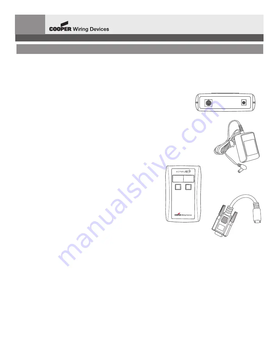
Step 1 – Apply Power to Serial Interface Programming Module (Figure 1)
Insert male connector of 5 VDC Power Adapter into Module and plug Power
Adapter into receptacle.
Open back compartment and insert two AA batteries into module.
NOTE:
Battery operation provides mobility to use Module as commissioning
tool to include/exclude Z-Wave devices into network.
NOTE
: When the Module is disconnected from its power adapter it is running
on batteries. If left on batteries, it will exhaust the batteries in two days. When
not adding devices, keep the Module connected to its power adapter, or
remove the batteries. The display will flash “b” while the unit is on batteries as a
reminder.
Step 2 – Adding Z-Wave devices to Serial Interface Programming Module
(Figure 2)
1. If RS232 cable has been connected to the Module please disconnect the Module from the serial
connection and bring the controller over to your Z-Wave device, such as lamp module or wall switch.
2. Hold down the “Add/Scan” button, and then press the inclusion button on the device you want to add.
NOTE:
If the device was previously added to a remote, or the device is not recognized, the Module’s display will not change. In this case
hold down the “Delete” button and press the inclusion button on the device. This will remove the device from the network and you can use
the “Add/Scan” button to add the device.
3. After the device is added, the display on the Module will show the node ID of the device. The node ID is a unique number in the range of
1 to 232. Write down this number as you will need to know it later if the device is added to ASPIRE RF HS2-Pro software.
NOTE
: When adding devices to the Module you need to be within one foot of the device.
Step 3 – Attaching RS232 Cable to Serial Interface Programming Module (Figure 3)
Attach S-video connector end of RS232 cable to Serial Interface Module and DB9 connector side to CPU or third party controller.
Note:
6 ft. extension cord is provided with module for longer cable runs.
OPERATION
7-segment LED Display
The 7-segment LED displays the node ID of the device when you include it into the network. It will display “b” when it’s on battery power,
A/C when it’s connected to its power adapter, “conn” when it’s connected to the PC serial port, “disC” when it’s disconnected from the
serial port and displays Add and Del messages when you are working with devices. When on batteries, it will display the amount of power
left in the batteries. All LED indications are momentary.
Creating Secondary Controller:
If you would like to use ASPIRE RF handheld (RFHDCSG) or tabletop (RFTDCSG) controllers, you need to copy Z-Wave information from
the Module to the controller using the “Replication” feature. Please reference the ASPIRE RF User Guide for the controllers for detailed
instructions (can be viewed or downloaded online at
www.cooperwiringdevices.com/ASPIRERF
) and the RF232 Tech Note referenced at
the top of the instruction sheet.
Retrieving Node IDs:
To retrieve the node ID (number), position the Module within one foot of the Z-Wave device in question, then press and release the “Add”
button. Dots will scroll across the display. Now press the inclusion button on the Z-Wave device. The Module will display the node number of
the device.
ENGLISH
IN U.S.A.:
Cooper Wiring Devices, 203 Cooper Circle, Peachtree City, GA 30269 • 866-853-4293
R
RFF223322 Z
Z--W
WA
AV
VE
E
®
®
S
SE
ER
RIIA
ALL IIN
NT
TE
ER
RFFA
AC
CE
E P
PR
RO
OG
GR
RA
AM
MM
MIIN
NG
G M
MO
OD
DU
ULLE
E ((A
AS
SC
CIIII))
RF232-PT (REV. A)
WIRELESS CONTROL SYSTEM
Delete
Add/Scan
www.cooperwiringdevices.com/AspireRF
FIGURE 1: TOP VIEW
FIGURE 2
FIGURE 3