background image

KEYBOARD FUNCTIONS

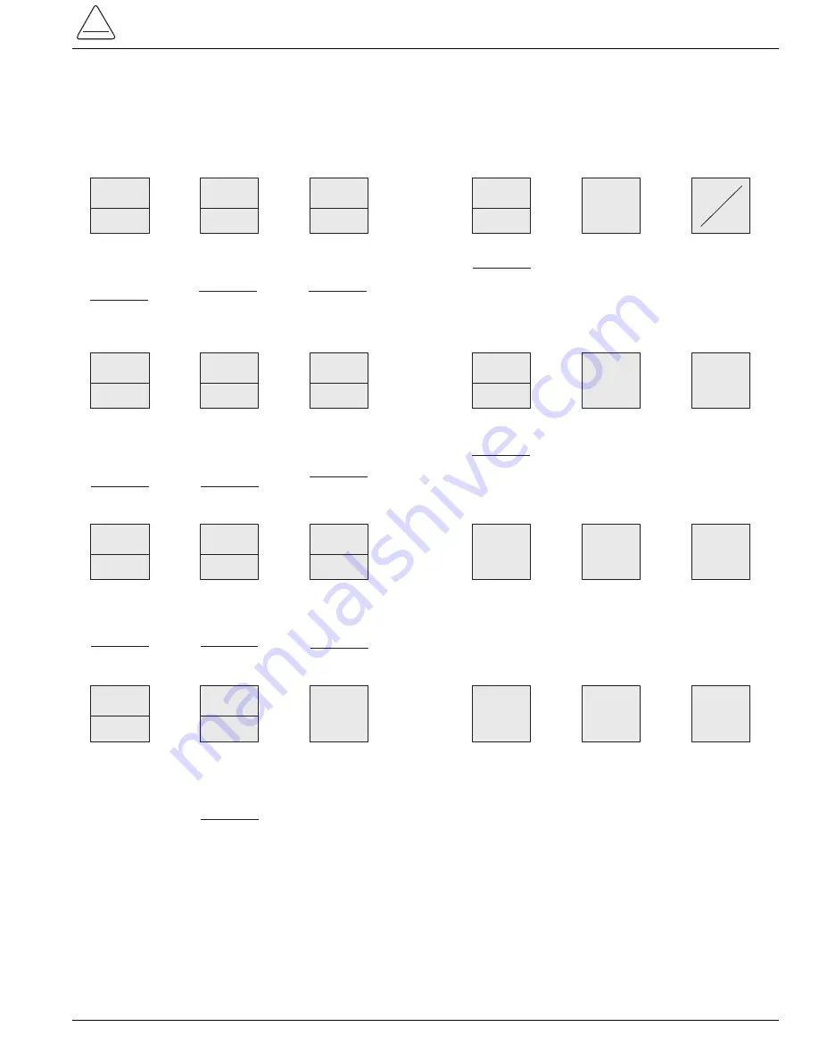
Prior to interrogation and programming, the operator should be familiar with the control’s keyboard. Figure 2 shows
each key and its description of operation.

5

S280-77-4

!

SAFETY

FOR LIFE

MINIMUM

TRIP

1

Interrogates or 

programs 

minimum trip 

(Phase and 

Ground)

"1" numeric 

value

OPER

1ST TCC

4

Interrogates or 

programs 

number of trip 

operations on 

1st TCC (Phase 

and Ground)

"4" numeric 

value

RECLOSE

1

7

Interrogates or 

programs 

reclosing time 

after 1st trip 

operation 

"7" numeric 

value

PHASE

GROUND

Toggles 

between Phase 

and Ground 

Display

TCC1

2

Interrogates or 

programs 1st 

TCC (Phase 

and Ground)

"2" numeric 

value

OPER

TO L.O.

5

Interrogates or 

programs 

number of 

operations to 

lockout (Phase 

and Ground)

"5" numeric 

value

RECLOSE

2

8

Interrogates or 

programs 

reclosing time 

after 2nd trip 

operation

"8" numeric 

value

DISPLAY

TEST

0

Checks LCD 

operation by 

displaying all 

numeric 

segments and 

messages

"0" numeric 

value

Interrogates or 

programs 2nd 

TCC (Phase 

and Ground)

"3" numeric 

value

TCC2

3

RESET

TIME

6

Interrogates or 

programs reset 

after successful 

reclose time 

delay 

"6" numeric 

value

RECLOSE

3

9

Interrogates or 

programs 

reclosing time 

after 3rd trip 

operation

"9" numeric 

value

SCROLL

Permits display 

of the 

programmed 

values of most 

common control 

operating 

features

Displays fault target 

information

Displays cumulative 

total of fault current 

trip phase  and 

ground.  (Used with 

SELECT LOWER 

FUNCTION key)

TARGETS

TARGET

COUNTERS

Displays total 

number of control 

trip operations

Displays control 

operating sequence 

position.  (Used with 

SELECT LOWER 

FUNCTION key)

OPER.

COUNTER

SEQUENCE

POSITION

Displays status of 

individual control 

features with 

programmable 

values

SELECT

ACCESSORY

Provides access to 

Target Counters and 

Sequence Position

SELECT

LOWER

FUNCTION

Displays Phase 

and Ground load 

current and 

demand metering 

readings

CURRENT

METERING

Provides direct entry 

of access codes

CODE

Displays individual 

parameters of 

programmable 

control features and 

accessories

ACCESSORY

SCROLL

Escape key ignores 

recent keystroke and 

returns to ready 

(rdY) prompt

ESCAPE

Turns keyboard 

and display ON 

and OFF

OFF

DISPLAY
ON

Clears pending 

keyboard entries; 

resets targets, 

counters and 

demand drag hand

CLEAR

Initiates change to 

programmed 

parameter

CHANGE

Enters changed 

parameter into 

program

ENTER

Figure 2.
Keyboard Functions.

Summary of Contents for Kyle Form 4C

Page 1: ...ogation Using the Select ACCESSORY Key 11 Control Interrogation Using the ACCESSORY SCROLL Key 11 Downloading to a Data Reader 12 Control Operation with a Personal Computer 13 Control Interface Software Program 13 Standard Access Codes and Parameters 14 Accessory Access Codes and Parameters 16 Access Code Descriptions 17 1 Reclosers Kyle Form 4C Microprocessor Based Recloser Control Programming Gu...

Page 2: ...ng or testing this equipment carefully read and understand the contents of this manual Improper operation handling or maintenance can result in death severe personal injury and equipment damage G101 0 SAFETY FOR LIFE Cooper Power Systems products meet or exceed all applicable industry standards relating to product safety We actively promote safe practices in the use and maintenance of our products...

Page 3: ...criptions are also listed on the control information label located inside the cabinet door CAUTION Equipment misoperation Do not connect this control to an energized recloser until all control settings have been properly pro grammed and verified Refer to the programming information for this control Failure to comply can result in control and recloser misoperation equipment damage and personal inju...

Page 4: ...rating parameters Minimum trip values Number of operations to lockout Time current curves Reclose time Current transformer selection Supervisory close reset time Phase identification Feature ON OFF commands Selection of metering integration intervals Access to TCC timing groups Activation of Sensitive Ground Earth Fault High Current Trip and High Current Lockout Event Recorder Duty Cycle Monitor F...

Page 5: ...se time delay 6 numeric value RECLOSE 3 9 Interrogates or programs reclosing time after 3rd trip operation 9 numeric value SCROLL Permits display of the programmed values of most common control operating features Displays fault target information Displays cumulative total of fault current trip phase and ground Used with SELECT LOWER FUNCTION key TARGETS TARGET COUNTERS Displays total number of con...

Page 6: ...To set the date 1 Press the SCROLL key to advance the control to Access Code 154 Code 154 can also be entered manually 2 Press CHANGE Enter four digits for the month 01 to 12 and day 01 to 31 Single digit months and days are preceded by a zero Press ENTER To set hour and minute 1 Press SCROLL to advance the control to Access Code 155 Code 155 can also be entered manually 2 Press CHANGE and enter f...

Page 7: ...alifies him to make changes to control settings The security code must be re entered if the display is turned off or shuts off automatically after 10 minutes with no fur ther keyboard entry This feature ensures that the Form 4C control returns to the read only security access mode after the programming operator leaves the control The control can be programmed via the keyboard independent of the po...

Page 8: ...CROLL CODE CHANGE GROUND Display Message Access Code Complex TCC Parameter Value CODE VALUE CODE VALUE CODE VALUE ENTER 4 EXAMINE PHASE SCROLL CODE CHANGE GROUND CODE VALUE 9 RECLOSE 3 9 SCROLL CODE MIN TRIP 7 CODE VALUE 1 CHANGE 8 EXAMINE PHASE SCROLL CODE CHANGE GROUND CODE VALUE 5 EXAMINE PHASE SCROLL CODE CHANGE GROUND EXAMINE PHASE SCROLL CODE CHANGE GROUND CODE VALUE As the security code is ...

Page 9: ...a parameter without a phase and ground value the control will ignore the command 9 S280 77 4 SAFETY FOR LIFE Step No Touch Key 11 12 13 EXAMINE PHASE SCROLL CODE CHANGE GROUND EXAMINE PHASE SCROLL CODE CHANGE GROUND EXAMINE PHASE SCROLL CODE CHANGE GROUND Display Message Access Code Complex TCC Parameter Value CODE VALUE CODE VALUE CODE VALUE ENTER 14 EXAMINE PHASE SCROLL CODE CHANGE GROUND CODE V...

Page 10: ...m 60 A to 120 A 10 Kyle Form 4C Microprocessor Based Recloser Control Programming Guide ENTER RECLOSE 3 Step No Touch Key 1 6 CODE 2 3 CODE VALUE EXAMINE PHASE SCROLL CODE CHANGE GROUND Display Message Access Code Complex TCC Parameter Value CODE VALUE CODE VALUE VALUE ENTER 4 EXAMINE PHASE SCROLL CODE CHANGE GROUND CODE VALUE 9 RECLOSE 3 9 SCROLL CODE 7 CODE VALUE DISPLAY ON EXAMINE PHASE SCROLL ...

Page 11: ...Code 130 High Current Lockout Code 140 This allows the operator a quick overview of modifica tions to the control parameters without individual code selection Control Interrogation Using The Accessory SCROLL Key Some features on the Form 4C control contain multiple settings These features are Complex TCC1 Code 100 through 104 Complex TCC2 Setup Code 110 through 114 Sensitive Ground Earth Fault Cod...

Page 12: ...on 3 01 To operate the Data Reader 1 Connect the Data Reader to the data port Figure 2 2 Press and hold the START DATA READING button All three LED lights will illuminate 3 When the READING and READING COMPLETE lights go out release the START DATA READING button The BATTERY OK light will remain illuminated The READING light will illuminate and remain on while the data reader obtains data from the ...

Page 13: ...ystem 16 MB of RAM and a 266 MHz Intel Pentium processor CONTROL OPERATION WITH A PERSONAL COMPUTER A Data Port to Computer Interface Cable is available to permit connection of a personal computer to the data port on the front panel of the Form 4C control The inter face cable consists of an EIA232 connector on one end and a data port 9 pin connector on the other end The cable includes an adapter t...

Page 14: ... Ground Trip Precedence 26 Supervisory Via Momentary Contact TARGETS 30 Target Status Reset 32 Target Counter Ground 33 Target Counter Phase 1 2 34 Target Counter Phase 3 4 35 Target Counter Phase 5 6 36 Target Counter Sensitive Ground Fault SEQUENCE POSITION 38 Sequence Position OPERATIONS COUNTER 39 Operations Counter METERING 40 Instantaneous Current Ground 41 Instantaneous Current Phase 1 2 42...

Page 15: ...sitive Ground Earth Fault Status HIGH CURRENT TRIP 130 High Current Trip Phase ON OFF 131 High Current Trip Ground ON OFF 132 High Current Trip Multiple of Minimum Trip Phase and Ground 133 High Current Trip Trip Time Delay Phase and Ground 134 High Current Trip Active Shot Number Phase and Ground HIGH CURRENT LOCKOUT 140 High Current Lockout Phase ON OFF 141 High Current Lockout Ground ON OFF 142...

Page 16: ...keypad are also available for status The firmware accessories include the Optional Universal I O board as part of the design for access to the CPU control points and status points Each status point is available via a single pole double throw contact Serial communications are also included for all the avail able firmware accessories and documented in Refer ence Information R280 90 11 Communications...

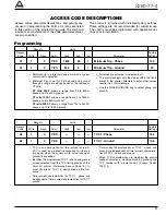
Page 17: ...CT ratio 2000 1 allows a range from 100 to 2400 A phase and 10 to 1600 A ground All values are adjusted in increments of 1 The control accepts only the values within the limits preset in the control Attempts to enter other values results in a LO HI message Use the PHASE GROUND key to select phase and ground Security Limits Access Factory Code Write Read Scroll High Low Incr Parameter Settings 02 1...

Page 18: ...is tics of TCC1 phase and ground When TCC characteristics are modified the control readout indicates a modified curve by prefixing the TCC number with a lower case c Access Codes 100 114 Security Limits Access Factory Code Write Read Scroll High Low Incr Parameter Settings 04 1 0 YES 4 0 1 Operations on TCC1 Phase 2 04 1 0 YES 4 0 1 Operations on TCC1 Ground 2 Selection of zero to four trip operat...

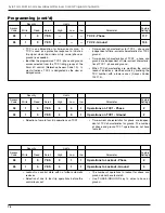
Page 19: ... second trip operation Security Limits Access Factory Code Write Read Scroll High Low Incr Parameter Settings 07 1 0 YES 45 0 0 3 0 1 Reclose 1 seconds 2 Reclose 1 is the open time duration after the first trip operation prior to automatic reclosing Selects the reclose interval after the first trip operation Programming cont d Security Limits Access Factory Code Write Read Scroll High Low Incr Par...

Page 20: ... TRIP front panel switch or through supervisory control Setting the alternate minimum trip values equal to the values in Access Code 01 disables Access Code 11 Programming cont d Security Limits Access Factory Code Write Read Scroll High Low Incr Parameter Settings 10 1 0 NO 2000 500 CT Selection 1000 Programs the control to operate with a recloser cur rent transformer ratio of 500 1 1000 1 or 200...

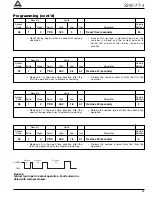
Page 21: ...ence coordination feature is not operative on the last oper ation The feature will not advance the control if advancing produces lockout If non reclosing is activated the Sequence Coordi nation feature is disabled Security Limits Access Factory Code Write Read Scroll High Low Incr Parameter Settings 21 1 0 YES Target Reset After Successful Reclose ON ON OFF Select the Target Reset feature ON and O...

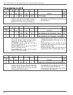
Page 22: ...s Access Factory Code Write Read Scroll High Low Incr Parameter Settings 24 1 0 YES Recloser Duty Monitor ON OFF ON With feature ON the recloser duty is recorded for each individual phase Access Codes 170 through 173 The Recloser Duty Monitor automatically returns to the ON position when the front display is OFF Select Recloser Duty Monitor ON or OFF using the CHANGE key Security Limits Access Fac...

Page 23: ...d number of phase operations to lockout Minimum Trip Phase Access Code 01P 200 A Minimum Trip Ground Access Code 01G 100 A TCC1 Phase Access Code 02P 103 TCC1 Ground Access Code 02G 101 TCC2 Phase Access Code 03P 133 TCC2 Ground Access Code 03G 135 Operations on TCC1 Phase Access Code 04P 2 Operations on TCC1 Ground Access Code 04G 1 Operations to Lockout Phase Access Code 05P 4 Operations to Lock...

Page 24: ...he TARGET COUNTER key the first time displays the cumulative number of ground trip operations Continuous scrolling with the TARGET COUNTER key advances the display to show the cumulative number of trip operations for each phase and Sensitive Ground Earth Fault When the Sensitive Ground Earth Fault feature is ON the Target Display is altered to distinguish between sensitive ground earth fault trips...

Page 25: ...transformers mounted within Kyle electronically controlled reclosers current metering data is shown on the control panel LCD dis play eliminating the need for separate meters and bushing current transformers Current metering in the Form 4C control monitors in rms A Instantaneous current values Phase demand current values integrated over a programmable time interval of 5 or 15 minutes Ground demand...

Page 26: ...or OFF status of Hot Line Tag Hot Line Tag is selected either by the front panel HOT LINE TAG switch or from supervisory control Security Limits Access Factory Code Write Read Scroll High Low Incr Parameter Settings 57 1 0 NO 15 5 Select Integration Interval Phase 5 5 or 15 minutes 57 1 0 NO 5 1 Select Integration Interval Ground 1 1 or 5 minutes Changes integration time value of demand metering U...

Page 27: ...ings 65 Reset 0 0 NO Accessory Status Codes 1 High Current Lockout 2 Remote Trip and Lockout 3 Supervisory Trip and Lockout Identifies the specific operation as indicated by the Accessory Operation LCD indicator on the control panel Reset with CLEAR key Security Limits Access Factory Code Write Read Scroll High Low Incr Parameter Settings 68 0 NO Trip On TCC2 Status Appicable to controls with CPU ...

Page 28: ...d provides a cross reference to the Form 3A control equivalents The curves are arranged in four keyboard accessible timing groups Each timing group contains a selection of 21 TCC s Curves 200 201 and 202 in timing group 4 match IEC curves normally described as inverse very inverse and extremely inverse respectively Time current curves can also be selected and programmed via the data port or remote...

Page 29: ...mware Version Y XX Y represents the version of the CPU firmware XX represents the protocol used EXAMPLE Y 14 represents CPU firmware with Protocol 2200 Y 15 represents CPU firmware with Protocol 2179 8 XX includes Hot Line Tag HLT and Switch Mode 9 XX includes HLT and Sensitive Ground Fault SGF 10 XX includes HLT and Trip on TCC2 TCC2 11 XX includes Switch Mode and TCC2 12 XX includes Switch Mode ...

Page 30: ...otocol used EXAMPLE Z 14 represents display board firmware with Proto col 2200 Z 15 represents display board firmware with Proto col 2179 IMPORTANT The version number suffix of the CPU Access Code 72 and the Display firmware must be identical Firmware Version Control Identification cont d Security Limits Access Factory Code Write Read Scroll High Low Incr Parameter Settings 77 0 NO CPU Firmware Re...

Page 31: ... de energized no ac or dc power while in the close retry mode it does not remem ber that it is in the close retry mode upon re energiza tion When the control is re energized it goes to the same state as the recloser If the recloser is open the control goes to lockout When the control and recloser are locked out and the operator attempts to close the recloser either with the Manual Control Switch o...

Page 32: ... Settings 81 0 0 NO 6 1 1 Real Time Digital Communications Port 2 Baud Rate 1 300 2 1200 3 2400 4 4800 5 9600 6 19200 Shows the baud rate of the real time digital commu nications port The baud rate code 1 6 must correspond to the baud rate of the system Baud rates are selectable through the keyboard Transmit speed always equals receive speed Changes to the baud rate require re energizing the contr...

Page 33: ...er powered EIA 232 and 202T modem interface Mode 2 is used where a transmit enable push to talk is required as part of the handshaking Applications include using the transmit enable to key a radio along with using a fiber optic ring Transmit enable is required for control of the fiber optic ring Mode 3 Transmit Enable with 0 millisecond transmit disable delay This application is identical to Mode ...

Page 34: ...i od The control is now synchronized so that the next byte received is considered the beginning of a new message The value programmed is the equivalent number of characters that the receive line must remain inac tive to be considered the end of a message The control determines the actual time delay internally taking into account baud rate and the number of bits in the character For example Baud 48...

Page 35: ...e Tagged Reset ON or OFF using the CHANGE key ON position reports only data that occurred since the last time the event recorder or load profile was polled OFF position reports the entire content of the event recorder and load profile regardless of the data pre viously downloaded This change affects Protocol 2179 only through the communication serial port This has no effect on the time tagged buff...

Page 36: ...access to special operating features Security Limits Access Factory Code Write Read Scroll High Low Incr Parameter Settings 91 3 3 NO 9999 0 1 Level 2 Security Access 2222 Level 2 permits modifications of special features IMPORTANT Level 2 must only be accessi ble to personnel completely familiar with the special features Security Codes Security Limits Access Factory Code Write Read Scroll High Lo...

Page 37: ...e PHASE GROUND key to examine phase and ground Default setting when TCC1 is changed from Access Code 02 key 2 The Form 4C control is equipped with 41 standard keyboard selectable time current curves interchangeable for phase and ground TCC1 and TCC2 Access codes 100 through 114 apply modifiers to the stan dard curves to assist in system coordination A time current curve modifier example is present...

Page 38: ...ase cycles 104 1 0 YES 42 0 1 TCC1 Minimum Response Time 0 Ground cycles Allows modification of the programmed TCC1 by selecting a minimum response time in a range from 0 to 42 cycles Use with the PHASE GROUND key to modify phase or ground TCC1 Default setting when TCC1 is changed from Access Code 02 key 2 Time Current Curve Modifiers cont d Security Limits Access Factory Code Write Read Scroll Hi...

Page 39: ...t of Code 111 will indicate a modified curve by prefix ing the TCC with a lower case c Access Codes 111 or 03 can be used to examine TCC2 Changes to Access Code 111 automatically update Access Code 03 Changes to Access Code 03 automatically update Access Code 111 Security Limits Access Factory Code Write Read Scroll High Low Incr Parameter Settings 112 1 0 YES 0 20 0 00 0 01 TCC2 Constant Time Add...

Page 40: ...om 0 to 42 cycles Use with the PHASE GROUND key to modify phase or ground TCC2 Default setting when TCC2 is changed from Access Code 03 key 3 Time Current Curve Modifiers cont d Security Limits Access Factory Code Write Read Scroll High Low Incr Parameter Settings 113 1 0 YES 2 00 0 10 0 01 TCC2 Multiplier Value Phase 1 00 113 1 0 YES 2 00 0 10 0 01 TCC2 Multiplier Value Ground 1 00 Vertically shi...

Page 41: ...e 103 and 113 for interrogation and programming Time Current Curve Modifiers cont d 30 20 10 8 6 5 4 3 2 1 8 6 5 4 3 2 0 1 08 06 01 02 03 04 05 50 60 80 100 200 300 400 500 600 800 1000 2000 3000 4000 5000 6000 8000 10000 20000 30000 40000 50000 CURRENT percent of minimum trip TIME sec TIME cycles 60 Hz basis 0 6 1 2 1 8 2 4 3 0 3 6 4 8 6 0 12 18 24 30 36 48 60 120 180 240 300 360 480 600 1200 180...

Page 42: ...0 120 180 240 300 360 480 600 1200 1800 High Current Trip Level 10x Trip Time Delay in 2 cycles 133 30 20 10 8 6 5 4 3 2 1 8 6 5 4 3 2 0 1 08 06 01 02 03 04 05 50 60 80 100 200 300 400 500 600 800 1000 2000 3000 4000 5000 6000 8000 10000 20000 30000 40000 50000 CURRENT percent of minimum trip TIME sec TIME cycles 60 Hz basis 0 6 1 2 1 8 2 4 3 0 3 6 4 8 6 0 12 18 24 30 36 48 60 120 180 240 300 360 ...

Page 43: ...ec TIME cycles 60 Hz basis 0 6 1 2 1 8 2 4 3 0 3 6 4 8 6 0 12 18 24 30 36 48 60 120 180 240 300 360 480 600 1200 1800 2400 3000 3600 6 5 CURRENT percent of minimum trip 1 2 3 4 30 20 10 8 6 5 4 3 2 1 8 6 5 4 3 2 0 1 08 06 01 02 03 04 05 50 60 80 100 200 300 400 500 600 800 1000 2000 3000 4000 5000 6000 8000 10000 20000 30000 40000 50000 CURRENT percent of minimum trip TIME sec TIME cycles 60 Hz ba...

Page 44: ...Trip Level is set as a per centage of programmed ground minimum trip in the range of 10 to 100 in 1 increments with 3 A as the minimum allowable trip value Form 4C control logic will prevent changes in the percentage settings that would give a trip value below 3 amps Under this condition an LO message will appear in the display Subsequent changes to the Ground Earth Minimum Trip setting Access Cod...

Page 45: ...the Sensitive Ground Earth Fault feature The setting is independent of the Number of Opera tions to Lockout Access Code 05 set for normal phase and earth trip operations IMPORTANT Any combination of Sensitive Ground Earth Fault and phase and ground operations will not exceed four operations to lockout Security Limits Access Factory Code Write Read Scroll High Low Incr Parameter Settings 125 0 NO S...

Page 46: ...ordination with primary substation transformer protection or coordination with load side fusing Trips a recloser at any current above the selected fault current level Levels are set as multiples of the minimum trip see Access Code 132 High Current Trip Ground is operable for phase and ground combined It does not operate for ground only Select High Current Trip Ground ON and OFF using the CHANGE ke...

Page 47: ...se the PHASE GROUND key to examine phase or ground High Current Trip cont d Security Limits Access Factory Code Write Read Scroll High Low Incr Parameter Settings 133 1 0 YES 9 1 High Current Trip Phase cycles 1 Trip Time Delay 133 1 0 YES 9 1 High Current Trip Ground cycles 1 Trip Time Delay Time delays are selectable from 1 to 9 cycles in increments of 1 cycle based on 60 Hz For 50 Hz systems mu...

Page 48: ...Current Lockout allows for tripping the recloser with a programmable operating sequence whenever fault current exceeds a programmed level High Current Lockout is used to modify the operat ing sequence to allow for reduced through faults on the substation transformer and connected equipment Locks out a recloser at any current above the select ed fault current level Levels are set as multiples of th...

Page 49: ...imits Access Factory Code Write Read Scroll High Low Incr Parameter Settings 156 0 0 YES 59 00 01 Set Time Clock Seconds 00 If the number of seconds is a single digit the digit is preceded by a zero High Current Lockout cont d Security Limits Access Factory Code Write Read Scroll High Low Incr Parameter Settings 143 1 0 YES 4 1 High Current Lockout Phase 4 Active Trip Number 143 1 0 YES 4 1 High C...

Page 50: ...6 1 2 08 9 21 07 1 30 0 13 1 30 0 14 7 1 2 08 9 21 05 1 30 0 13 1 30 0 14 8 1 2 08 9 21 03 1 30 0 13 1 30 0 14 9 2 2 03 14 40 49 0 02 0 15 0 15 0 16 10 1 2 03 14 40 16 2 40 2 40 0 15 0 16 11 1 2 03 14 40 14 2 40 2 40 0 15 0 16 12 2 2 03 14 38 40 0 02 0 15 0 15 0 17 13 1 2 03 14 37 08 2 80 0 16 0 15 2 80 TABLE 8 Event Recorder Sample Data Security Limits Access Factory Code Write Read Scroll High L...

Page 51: ...nation 12 Sensitive Ground Earth Fault Trip 13 Close Retry Lockout 14 Fault Target Switch Mode 15 Switch Mode 16 Recloser Mode 17 Recloser Manual Lockout yellow handle is down 18 Attempt To Close When Hot Line Tag Is Active 19 Unknown Event DOS Inconsistent State Lockout CCI Interface software 20 Alternate Minimum Trip is ON 21 Alternate Minimum Trip is OFF Code 19 An Event Type 19 is logged in th...

Page 52: ...9 0 YES Phase Bushing 5 6 Current kA Access Codes 167 through 169 identify the current through the three phases of the event indicated by Access Code 161 Current values are in rms kiloamperes Current range is from 0 kA to 30 times programmed minimum trip value If the fault exceeds 30 times minimum trip an over range message 1 will be displayed Access Codes 167 through 169 can only be accessed from...

Page 53: ...ing duty reaches 100 the interrupter contacts should be examined and replaced The Duty Cycle Monitor provides keyboard accessible duty cycle information The Duty Cycle measures and records duty for each indi vidual phase in non volatile memory The recloser duty is measured and stored on the basis of Cur rent1 5 x Number of Operations for Each Phase ANSI C37 61 Readout is based on a percentage of t...

Page 54: ...h phase and ground No security code is required for readout IMPORTANT Load Profile Data will be lost if power to the Form 4C control is lost Load Profile data will also be lost when the control resets after a change to a TCC Group Access Code 70 or Line Frequency Access Code 71 Security Limits Access Factory Code Write Read Scroll High Low Incr Parameter Settings 181 0 YES Time Hour and Minute Ind...

Page 55: ...t A 184 0 YES Phase Bushing 3 4 Current A 185 0 YES Phase Bushing 5 6 Current A Indicates the rms demand current profile for the three Phase Currents Load Profile Monitor Cont d Security Limits Access Factory Code Write Read Scroll High Low Incr Parameter Settings 182 0 YES Ground Current A Indicates the rms demand current profile for Ground Current ...

Page 56: ... 191 2 0 YES 800 5 1 Switch Mode Minimum 50 Target Sensing Ground Applicable to controls with CPU Firmware versions 8 XX 11 XX and 12 XX only Minimum target sensing is a threshold value at which a system overcurrent is detected Minimum target sensing is set for both phases and ground through a range of settings based on the recloser s CT ratio CT ratio 500 1 allows a range from 25 to 800 A phase a...

Page 57: ...nimum target sensing is set for both phase and ground through a range of settings based on the recloser s CT ratio CT ratio 500 1 allows a range from 25 to 800 A phase and 2 to 400 A ground CT ratio 1000 1 allows a range from 50 to 1600 A phase and 5 to 800 A ground CT ratio 2000 1 allows a range from 100 to 2400 A phase and 10 to 1600 A ground All values are adjusted in increments of one The cont...

Page 58: ...58 Kyle Form 4C Microprocessor Based Recloser Control Programming Guide ...

Page 59: ...59 S280 77 4 SAFETY FOR LIFE ...

Page 60: ... Inc Form 4C INTERFACE is a trademark of Cooper Industries Inc IBM PC XT AT and PS 2 are registered trademarks of IBM Corp Intel and Pentium are registered trademarks of the Intel Corporation in the U S and other countries Microsoft and Windows are either registered trademarks or trademarks of Microsoft Corporation in the United States and or other countries KA2048 446 Rev 02 KDL 2 03 SAFETY FOR L...

Reviews: