

Quick Guide
–
iDFace
–
Version 1.1
–
Control iD 2021 ©
iDFace
–
Quick Guide
Thank you for purchasing iDFace! To access detailed
information about your new product, please check the
following link:
www.controlid.com.br/userguide/idface-en.pdf
Necessary Materials
In order to install your iDFace, you will need the
following items: drill, wall plugs and screws,
screwdriver, 12V power supply rated for at least 1A
and an electronic lock.
Installation
For the correct operation of your iDFace, the following
precautions should be taken:
•
Install in a place that is not exposed to direct
sunlight. This lighting factor must be considered in
order to ensure the quality of the captured images.
•
Avoid metallic objects near the rear of the device in
order not to impair the proximity reader’s range. In
case this is not possible, use insulating spacers.
•
Before securing the device in place, ensure all
connecting cables are correctly routed towards the
device.
•
Fix the bottom part of the wall support for iDFace
at 1.35m from the ground for the passage of people
or at 1.20m for the recognition of a person inside a
car.
The device installation process is simple and should
follow the diagram below:
1.
For greater security during the installation, place
the External Access Module (EAM) in a secure
region (internal area of the facility).
2.
Use the reference pattern in the back of this guide
to drill the 3 holes required to install the iDFace and
fit the wall plugs in.
3.
Connect the EAM to a +12V power source and to
the lock using the cables supplied.
4.
Prepare a 4
–
way cable long enough to connect the
EAM to the iDFace. For distances greater than 5m,
use a twisted pair cable for the data signals. If you
choose a Cat 5 cable to connect the EAM to the
iDFace, use 3 pairs for power and 1 pair for the data
signals. In this case, the distance cannot surpass
25m. Remember to use the same pair for signals A
and B.
Recommended setup for Cat 5 cable
5.
Connect the wire harness provided with iDFace
to the 4 wires in the previous item.
6.
Remove the wall support from the iDFace.
7.
Screw the wall support with the wall plugs.
8.
Remove the sealing lid from the bottom and
connect the 4-way wire to the iDFace.
9.
Insert and fix the lid and the sealing rubber.
The lid and the sealing rubber are essential
for IP65 protection. Please make sure to position
and fix them on the back of the product properly.
10.
Secure the iDFace on the wall support and secure
it in place with the screws provided together with
the connection cables.
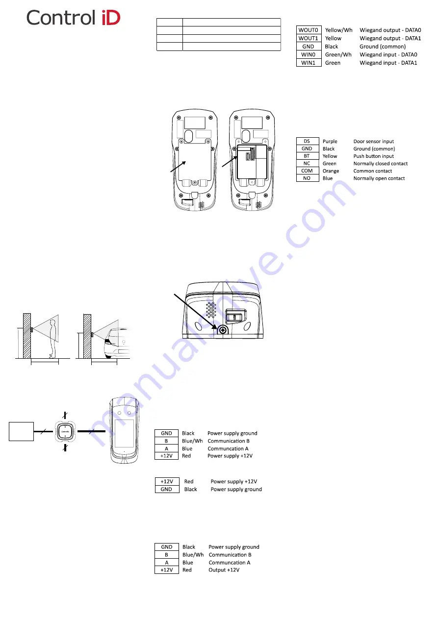
Description of the Connection Terminals
On your iDFace, there is a connector on the back of
the device, right next to the network connector
(Ethernet). In the External Access Module (EAM)
there is a matching connector and 3 other
connecting pins that will be used to connect locks,
switches and scanners as explained ahead.
iDFace: 4 - Pin Connector
EAM: 2 - Pin Connector (Power Supply)
The connection to a +12V power supply rated for
at least 1A is fundamental for the correct operation
of the device.
EAM: 4 - Pin Connector
EAM: 5 - Pin Connector (Wiegand In/Out)
External card readers should be connected to
Wiegand WIN0 and WIN1. In case there is a control
board, one can connect the Wiegand WOUT0 and
WOUT1 outputs to the control board so that the user´s
ID identified in the iDFace is transferred to it.
EAM: 6 - Pin Connector (Door Control/Relay)
The push button and door sensor inputs can be
configured as NO or NC and must be connected to dry
contacts (switches, relays etc.) between the GND and
respective pin.
iDFace Settings
The configuration of all the parameters of your new
iDFace can be set through the LCD display (Graphical
User Interface
–
GUI) and/or through a standard
internet browser (as long as the iDFace is connected to
an Ethernet network and have this interface enabled).
In order to configure, for example, the IP address,
subnet mask and gateway, through the touch screen,
follow these steps:
Menu
→
Settings
→
Network
.
Update the information as you wish and connect the
device to the network.
Web Interface Settings
First, connect the device directly to a PC using an
Ethernet cable (cross or direct). Next, set a fixed IP on
your computer for network 192.168.0.xxx (where xxx is
different from 129 so that there is no IP conflict) and
mask 255.255.255.0.
To access the device settings screen, open a web
browser
and
enter
the
following
URL:
http://192.168.0.129
The login screen will be shown. The default access
credentials are:
• Username:
admin
• Password:
admin
Through the web interface you can change the
device’s
IP. If you change this parameter, remember to
write down the new value so that you can connect to
the product again.
User Enrollment and Identification
The quality of a facial recognition system is directly
related to the quality of the image captured by the iDFace
during the enrollment stage. Thus, during this process,
please make sure that the face is aligned to the camera
and is 50 cm away
. Avoid atypical facial expressions and
objects that can hide important regions of the face (mask,
sunglasses and others).
m
m
m
m
Power
Supply
+12V
Relay, door sensor and push button
Wiegand input and output
Power supply for
iDFace and
communication
2
5
6
4
+12V
Green + Brown
GND
Green/Wh + Orange/Wh + Brown/Wh
A
Blue
B
Blue/Wh


