

Square Dual Load
Wireless Switch
Installation Guide
Introduction
The Control4® Square Dual Load Wireless Switch operates independently or
as part of a Control4 home automation system. It installs in a standard square
(UK/China-style) wall box using typical wiring standards and communicates to the
Control4 system using a wireless connection.
IMPORTANT!
This device must be installed in a standard square
UK/China-style single-gang wall box and use a single-gang EU
faceplate. It
cannot
be installed in a round EU-style wall box or in multi-
gang boxes.
Box contents
• Square Dual Load Wireless Switch
• Square Dual Load Wireless Switch Installation Guide
(this document)
• M3.5 machine screws (2)
• M4.0 machine screws (2)
Specifications and supported load types
Model numbers
C4-SDSW240-N
Power requirements
/-10%, 50/60 Hz
This device requires a neutral connection.
Power consumption
950mW
Load types and ratings
Supported load types
Incandescent, halogen, electronic (solid state)
low-voltage (ELV) transformer, magnetic (iron core,
inductive) low-voltage (MLV) transformer, compact
fluorescent, LED, and motor.
Maximum load per output
Incandescent (tungsten)
4A
Halogen
4A
Fluorescent
3A
Compact fluorescent (CFL)
3A
LED
1A
MLV
2A
ELV
2A
Motors
1/8 HP
Environmental
Operational temperature
0˚C ~ 40˚C (32˚F ~ 104˚F)
Humidity
5% to 95% non-condensing
Storage
-20˚C ~ 70˚C (-4˚F ~ 158˚F)
Miscellaneous
Control communications
ZigBee, IEEE 802.15.4, 2.4 GHz, 15-channel spread
spectrum radio
Wires per connector
One 0.5 mm
2
- 2.5 mm
2
OR
Two 0.5 mm
2
- 1.5 mm
2
Dimensions
81 × 81 × 30 mm (3.2 × 3.2 × 1.2 in.)
Depth in wall box
25.8 mm (1.0 in)
Weight
0.113 kg (0.25 lb)
Shipping weight
0.159 kg (0.35 lb)
Warnings and considerations
WARNING!
Turn OFF electrical power before installing or servicing
this product. Improper use or installation can cause SERIOUS INJURY,
DEATH or LOSS/DAMAGE OF PROPERTY.
WARNING!
This device must be protected by a circuit breaker
(20A max).
IMPORTANT!
This device must be installed by a licensed electrician in
accordance with all national and local electrical codes.
IMPORTANT!
This device requires a standard square UK/China-style
wall box. It cannot be installed in a round EU style wall box.
IMPORTANT!
Use this device only with copper or copper-clad wire. Do
not use aluminum wiring. This product has not been approved for use
with aluminum wiring.
IMPORTANT!
To reduce the risk of overheating and possible damage
to other equipment, do not install to control a receptacle or a motor
operated appliance.
IMPORTANT!
Using this product in a manner other than outlined
in this document voids your warranty. Further, Control4 is NOT
liable for any damage incurred with the misuse of this product. See
“Troubleshooting.”
IMPORTANT!
Do NOT use a power screwdriver to install this device
or to tighten wire screw terminals. If you do, you may overtighten the
screws and strip them. Also, overtightening the screws may interfere
with proper button operation.
IMPORTANT!
This is an electronic device with intricate components.
Handle and install with care!
IMPORTANT! Control4 does not guarantee the performance of any
bulb or lamp/fixture in your environment. CUSTOMER ASSUMES
ALL RISKS, INCLUDING ANY DAMAGE TO CONTROL4 PRODUCTS,
ASSOCIATED WITH (i) THE TYPE, LOAD RATING AND QUAILITY OF
THE BULB AND LAMP/FIXTURE, OR (ii) ANY USE OR INSTALLATION
NOT IN ACCORDANCE WITH THE DOCUMENTATION FURNISHED BY
CONTROL4, EITHER WITH THE CONTROL4 PRODUCT OR AT WWW.
CONTROL4.COM.
Installing the switch
1
Ensure that the location and intended use meet the following criteria:
• Do not exceed the load capacity requirements of the switch. Refer to the
load ratings in the specifications above for details.
• Install in accordance with all national and local electrical codes.
• The range and performance of the wireless control system is highly
dependent on the following: (1) distance between devices; (2) layout
of the home; (3) walls separating devices; and (4) electrical equipment
located near devices.
2
Turn off the mains electrical power at the consumer unit. To ensure the wires
do NOT have power running to them, use an inductive voltage detector.
3
Prepare each wire. Wire insulation should be stripped back 7 mm from the
wire end.
4
Identify your wiring application, and then see the appropriate wiring diagram
in the “Sample wiring configurations” section below.
5
Connect the switch to the wall box wires as shown in the applicable wiring
diagram. Tighten screw terminals to 4 kg-cm.
6
Fit the wires into the wall box.
7
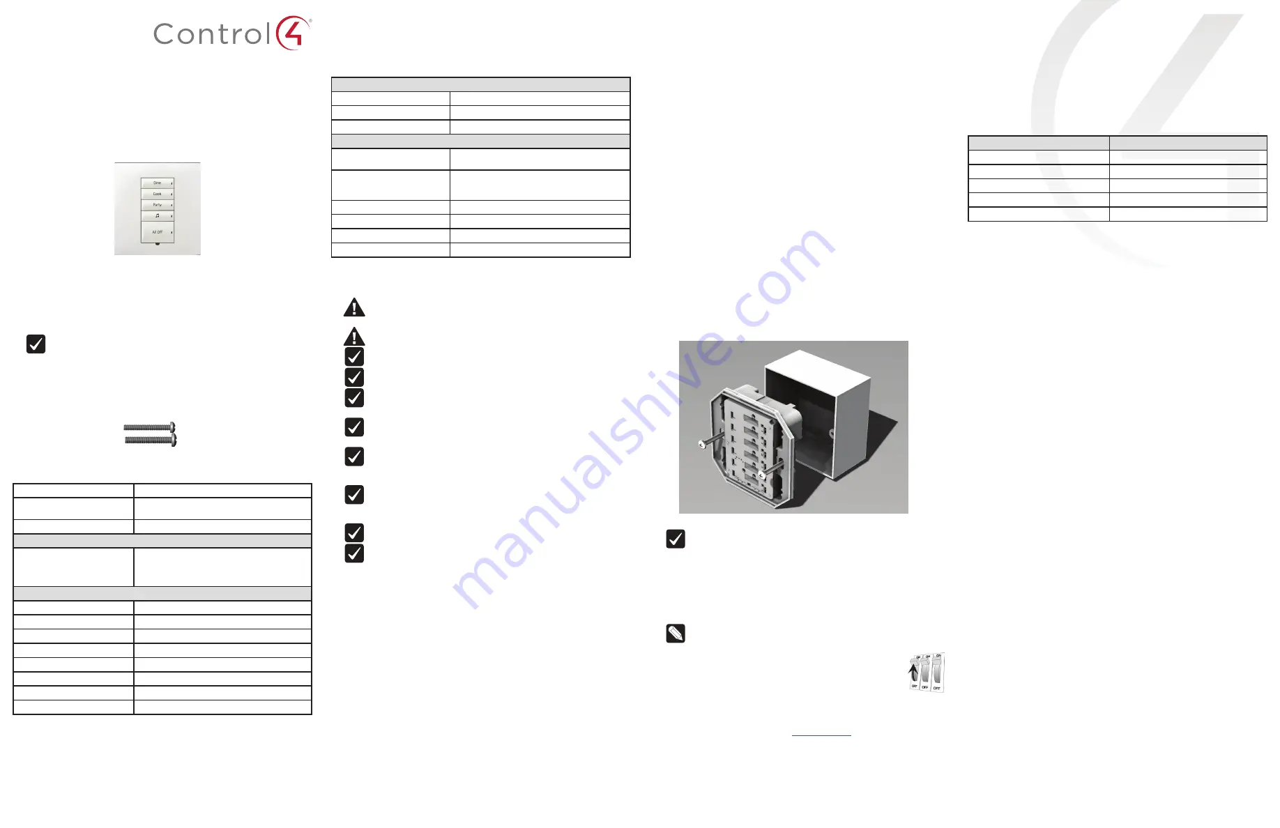
Align the switch to the wall box as shown in Figure 1 (note the
UP
orientation
arrow on the switch), then fasten the switch to the wall box using the
included M3.5 machine screws (UK-style wall box) or M4.0 machine screws
(China-style wall box).
Figure 1: Square wall box installation
IMPORTANT!
Tighten the screws until the device is flush with the wall
surface, but no further. Overtightening can warp the switch and cause it
to malfunction.
8
Attach the buttons (sold separately) as described in the
Keypad Button
Installation Guide
.
9
Install the Control4 Faceplate (sold separately) by placing the top of the
faceplate on the device (note the
UP
orientation arrow on the inside of the
faceplate) and firmly pressing the bottom until the faceplate snaps into place
against the wall.
Note:
To remove the faceplate, use a flathead screwdriver. Insert the
screwdriver into the small gap on the bottom between the faceplate
and the device, then twist the screwdriver blade to pop the faceplate
off.
10
Turn ON mains electrical power at the consumer unit.
Operating the switch
On initial power up, all status LEDs on the switch will illuminate green, indicating
that the device has power. To set up this switch for use with a Control4 system,
refer to the
Composer Pro User Guide
(
ctrl4.co/cpro-ug
).
To operate this switch as a stand-alone device before configuring in
Composer Pro or Composer Express:
• Any button in the top half of the keypad will toggle load 1 on and off.
• Any button in the bottom half of the keypad will toggle load 2 on and off.
Button tap sequences
The button tap sequences are defined in the table below. Button tap sequences
that require a single button should use the top-most button installed on the
switch. Button tap sequences requiring two buttons should use the top-most and
bottom-most buttons installed on the switch.
Function
Button tap sequence
Identify
4
ZigBee channel
7
Reboot
15
Factory reset
9-4-9
Leave mesh and reset
13-4-13
Troubleshooting
If the light does not turn on:
• Ensure that at least one LED on the face of the switch is lit.
• Ensure that the light bulb is not burned out and is screwed in tightly.
• Ensure that the circuit breaker is not turned OFF or tripped.
• Check for proper wiring (see “Sample wiring configurations”). If the Line and
Neutral wires are reversed, the light will be on while the switch is off, and vice
versa.
• For help on the installation or operation of this product, email or call the
Control4 Technical Support Center. Please provide your exact model number.
Contact [email protected] or see the web site
www.control4.com
.
Care and cleaning
• Do NOT paint the switch or its wall plate.
• Do NOT use any chemical cleaners to clean the switch.
• Clean surface of the switch with a soft damp cloth as needed.