BAST-321HP-B2
BACnet Communicating Thermostat for 2-stage Heat Pump Operation
BASstat
Heat Pump Thermostat
User Manual
# UM-15094000-AA0
Page 1: ...BAST 321HP B2 BACnet Communicating Thermostat for 2 stage Heat Pump Operation BASstat Heat Pump Thermostat User Manual UM 15094000 AA0...
Page 2: ...his publication may be reproduced transmitted transcribed stored in a retrieval system or translated into any language or computer language in any form or by any means electronic mechanical magnetic o...
Page 3: ...ntal 7 2 6 Electromagnetic Compatibility 7 2 7 Mechanical all dimensions are in mm 8 3 Installation 9 3 1 Terminal Block Pin Assignments 9 3 2 Limited Power Source 9 3 3 Power Supply Precautions 10 3...
Page 4: ...value can be sent by another communicating device over the BACnet network The BASstat is configurable locally using the Engineering Menu or via a network connection to a BACnet client Contemporary Co...
Page 5: ...as deadband proportional gain integral rate and cycle time Adjustable minimum maximum set point ranges Three options for temperature sensing o Built in temperature sensor or o Remote sensor RS input f...
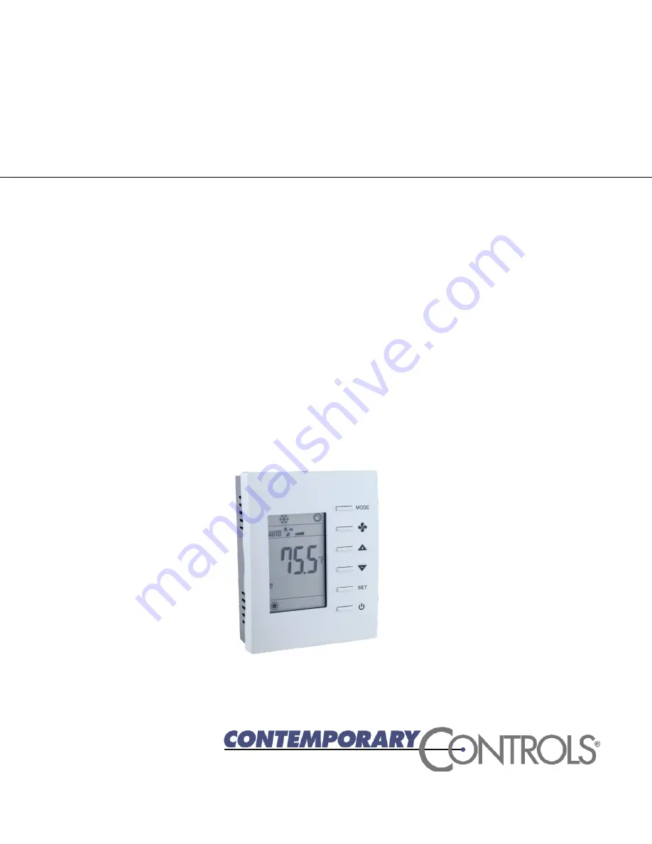
Page 6: ...UM 15094000 AA0 Page 5 1 2 Product Image and Main Features BASstat 321C B2...
Page 7: ...iption Relay Output Fan Compressor 1 Compressor 2 O B Reversing Valve Auxiliary Heat stage 3 Contact Rating SPST 2A at 30 VAC with inductive load Minimum contact life 100 000 cycles 2 3 Communication...
Page 8: ...andard Test Method Description EN 61000 6 2 IEC 61000 4 2 Electrostatic Discharge Immunity EN 61000 6 2 IEC 61000 4 3 Radiated Radio Frequency Electromagnetic Field Immunity EN 61000 6 2 IEC 61000 4 4...
Page 9: ...e 8 2 7 Mechanical all dimensions are in mm Mounts directly onto wall panel standard 65 65mm junction box hole pitch 60 mm or standard 2 4 inch vertical junction box hole pitch 83 5mm Width 94mm Heigh...
Page 10: ...inals 14 and 15 with a default setting of Open Occupied Closed Unoccupied The Outside Air Temperature OAT is wired to terminals 13 and 14 RS 485 is wired to terminals 16 and 17 Number Mark Comment Num...
Page 11: ...hat power several half wave devices have a common secondary connection called COMMON LO or GROUND Connect the HOT side of the secondary to the 24 VAC high side input on the BASstat and the LO side to...
Page 12: ...tates to start stop the thermostat outputs ON OFF control can be accomplished over BACnet as well 2 At power ON press any button to start the User Mode operation Press the MODE button to toggle betwee...
Page 13: ...Cnet supervisor 3 Mode Select Select the working mode Cooling Heating or Ventilating p After pressing the MODE button press the UP DOWN button to rotate the selections Dependent on Control Type 4 Fan...
Page 14: ...r will be presented with a choice of Heat or Ventilation Heat when the thermostat is in Heat mode automatic and Cool or Ventilation Cool when the thermostat is in Cool mode automatic Multi stage Cooli...
Page 15: ...ol algorithm is applied to minimize overshoot in addition to proportional band Stage Width and derivative Differential calculation When the thermostat is active either the heating or cooling stage is...
Page 16: ...cles the Clock icon will appear on the LCD Next Stage Engagement Short Cycle Delay There needs to be an automatic delay Short Cycle default 5 minutes E28 AV23 for cooling control E30 AV25 for heating...
Page 17: ...eat signal within the AV 29 Heartbeat Rate time period in seconds Otherwise the assigned temperature will revert back to the onboard sensor reading Fan Control Output Lowest Fan Speed is the speed the...
Page 18: ...state 0 for occupied and 1 for unoccupied AV18 is set as 0 by default When in unoccupied state a Moon icon will be displayed on the LCD and the thermostat will change the set point temperatures to th...
Page 19: ...another 10 seconds the display will return back to User mode Settings are not changed unless confirmed using the MODE button To leave Engineering Mode rotate till End menu item appears and press the M...
Page 20: ...0 0 1 C F E11 diFF Stage differential 0 5 0 1 1 0 1 0 0 1 1 8 0 1 C F 12 LOC Bit Definition 0 MODE button dec 1 1 Down buttons dec 2 2 Up button dec 4 3 FAN SPEED button dec 8 4 Power On Off button d...
Page 21: ...sed 0 0 100 0 0 100 1 E21 Baud Baud Rate 38 4 depends on Model Number 9 6 kbps 19 2 kbps 38 4kbps 57 6kbps 76 8kbps 38 4 depends on Model Number 9 6 kbps 19 2 kbps 38 4kbps 57 6kbps 76 8kbps E22 Addr...
Page 22: ...0 50 0 65 0 32 0 122 0 0 1 C F E47 HSPH Maximum Heating Temperature Setpoint 25 0 0 0 50 0 77 0 32 0 122 0 0 1 C F E48 nFAn Minimum Fan Output not used E49 hFAn Maximum Fan Output not used E50 FAnL Lo...
Page 23: ...reserved unused unused Bit Value 0 Unlock enable 1 Lock disable Add decimal values to lock multiples Bold decimal number is the example value to write to Lock object Examples Unlock enable all 0 this...
Page 24: ...configuration can also be altered using BACnet commands Network command based configuration can also be accomplished using a laptop computer tablet and Contemporary Controls free BACnet Discovery Tool...
Page 25: ...ent Dew Point 999 9999 99 9 999 9 F Current CO2 AI 6 R Current CO2 Reading 0 3000 0 3000 ppm Control Valve AI 7 R Control Valve Feedback 0 1000 0 0 100 0 Modulating Floating Output 1 AI 8 R Modulating...
Page 26: ...n recommended Unoccupied Cool Setpoint AV 8 R W Unoccupied Cooling Setpoint C 250 300 25 0 30 0 C F 770 860 77 0 86 0 F Unoccupied Heat Setpoint AV 9 R W Unoccupied Heating Setpoint C 100 220 10 0 22...
Page 27: ...Cnet sup 1 dec 512 10 15 reserved unused Bit Value 0 Unlock enable 1 Lock disable Examples add dec values to lock multiples For more details see Lock Function Setup and Examples section of this manual...
Page 28: ...ifferential for Humidity Control Output 0 1000 0 0 100 0 RH Proportional Band for stage width 2 AV 32 R W Stage Diff for humidity control 0 18 CO2 Offset AV 33 R W CO2 Offset Value 1000 2000 ppm After...
Page 29: ...ol 0 1000 0 0 100 0 RH Dew Point Set Point AV 50 R W Dew Point Temperature Set Point 999 9999 99 9 999 9 F Occupancy Status BI 0 R Status of Occupancy 0 Room Occupied 1 Room Unoccupied Window Door Sta...
Page 30: ...R Alarm Status 0 Off 1 On Frozen Alarm Status BI25 R Frozen Alarm Status 0 Off 1 On After Hour Status BI26 R After Hour Status 0 Normal Hour 1 After Hour Occupancy Contact Definition BV 0 R W Occupanc...
Page 31: ...an Mode 1 Auto 2 Low 3 Med 4 Hi System Mode MSV 1 R W Working Mode Heat Cool or Ventilation 1 Cool Mode 2 Heat Mode 3 Ventilation Cool Mode 4 Ventilation Heat Mode Sleep MSV 2 R W Sleep Only for Model...
Page 32: ...until it is received CC s limited warranty covers products only as delivered and does not cover repair of products that have been damaged by abuse accident disaster misuse or incorrect installation U...
Page 33: ...temporary Control Systems Inc Contemporary Controls Suzhou Co Ltd Contemporary Controls Ltd Contemporary Controls GmbH Tel 1 630 963 7070 Fax 1 630 963 0109 info ccontrols com Tel 86 512 68095866 Fax...