

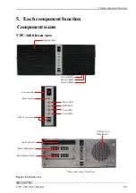


5. Each component function
72
VPC-1600 User’s Manual
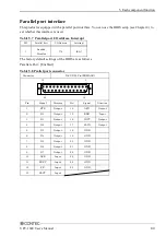
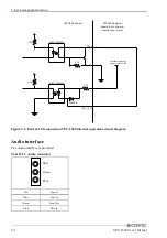
Digital I/O interface
For digital I/O, the JDIO1 and JDIO2 connectors are used to provide four inputs and two outputs.
Among the eight DIO pins, two output pins (O2, O3) are used for the user LED on the front.
The digital I/O interface is internally insulated.
Table 5.12 Digital I/O interface
JDIO1
JDIO2
Pin
Signal
Pin
Signal
1
I0
7
O0
2
I1
8
O1
3
I2
9
O2(Connected prohibition)
4
I3
10
O3(Connected prohibition)
5
PWRON
11
COMPO
6
RST
12
COMPI
1)I0 to I3 (JDIO1 Pin No. 1 to 4)
Input signal : You can input Input0, Input1, Input2, Input3, and Input4.
2)O0 to O3 (JDIO2 Pin No. 7 to 10)
Output signal : You can output Output1, and Output2.
*You can not use Output2,3 because they are used for the user LED on the front.
3)PWRON,RST (JDIO1 Pin No.5,6)
Short-circuiting PWRON and GND or RST and GND triggers the same operation as pushing
the Power button or Reset button on the front.
*However, the power-supply from the outside is necessary.
12
1
7
JDIO2
JDIO1
6
Summary of Contents for VPC-1600
Page 1: ...FA Computer Space Saving Model VPC 1600 User s Manual CONTEC CO LTD...
Page 15: ...1 Before Using the Product 8 VPC 1600 User s Manual...
Page 21: ...2 System reference 14 VPC 1600 User s Manual...
Page 49: ...3 Hardware setup 42 VPC 1600 User s Manual...
Page 69: ...4 BIOS setup 62 VPC 1600 User s Manual...
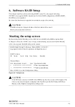
Page 97: ...6 Software RAID Setup 90 VPC 1600 User s Manual...